Traveling wave antenna

a technology of traveling wave and antenna, applied in the direction of resonant antenna, non-resonant long antenna, radiating element structural forms, etc., can solve the problem that the circuit board(s) are a significant factor in the total cost of the system

Inactive Publication Date: 2000-01-18
HOWELL LAB
View PDF12 Cites 51 Cited by
  • Summary
  • Abstract
  • Description
  • Claims
  • Application Information

AI Technical Summary

Benefits of technology

Presently known in the art are antennas which are directed to the passive market for outdoor wireless personal communication, operating in the 1850 to 1990 MHz range. Typically, these antennas are based on a low-profile flat panel design to cover the 30, 65, 85, 90 and 105 beamwidth requirements. The antennas are vertically polarized dipoles on an etched, high performance circuit board(s) on rigid aluminum channel-like back panels. The circuit board(s) are a significant factor in the total cost of the system.
The antennas of the present inv

Problems solved by technology

The circuit board(s) are a significant

Method used


Image

  • Traveling wave antenna
  • Traveling wave antenna
  • Traveling wave antenna

Examples


Embodiment Construction

)

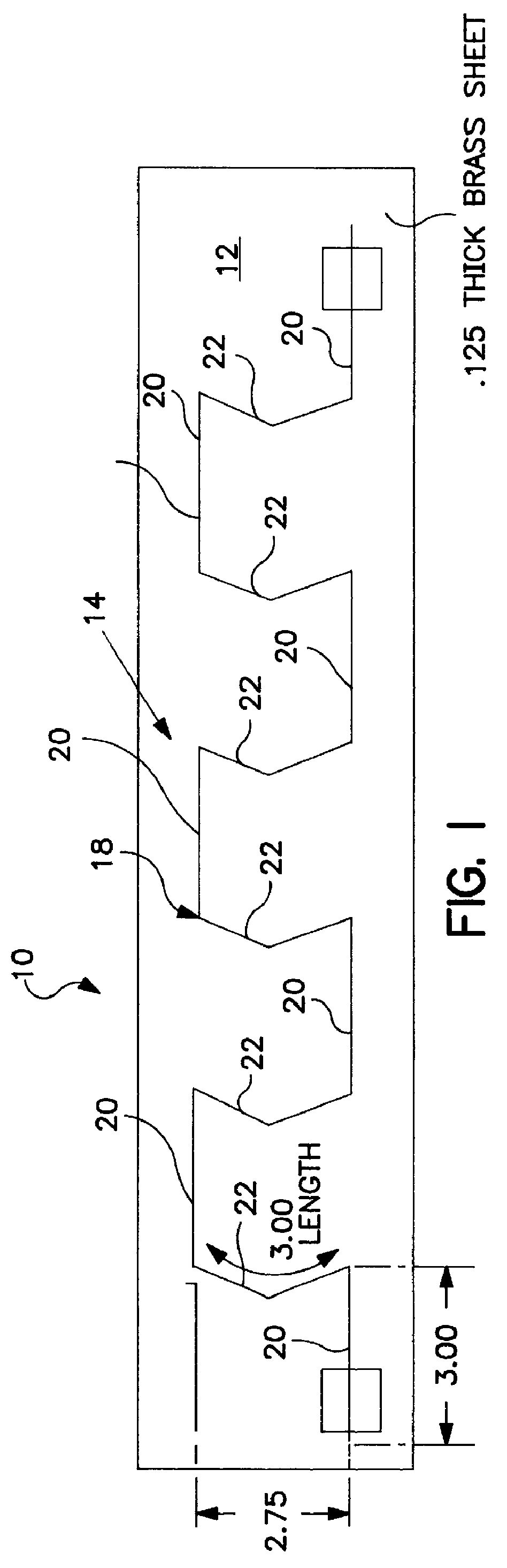
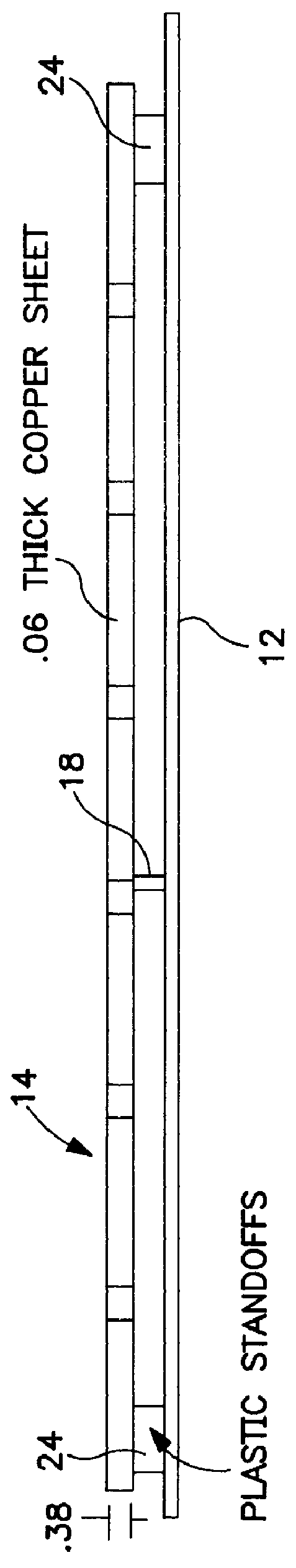
Referring to FIG. 1, an antenna is shown generally at 10 and comprises a planar ground plane 12, a copper radiator 14 secured to the ground plane by plastic insulators 24. The radiator 14 is a flat strip 3 / 8 inch wide and 1 / 16 inch thick. The radiator shown is formed by bending the strip with simple tools. Power is introduced to the radiator 14 via a feed point 18. The radiator arms 20 are .lambda. / 2 and three inches in length. They are joined at 90.degree. angles to V-like arms 22 which are .lambda. / 2 and 2.75 inches from end to end (original non V-length 3.00 inches). The radiator is spaced apart 1 / 2 inch from the ground plane (0.125 inches thick brass sheet) by Teflon.RTM. insulators 24. The specific feed lines, connectors, radome etc. associated with the antenna need not be described in detail these considerations being within the skill of the art. Based on the foregoing specifications, a 65.degree. radiation pattern (beamwidth) will be provided at 1920 MHz.

As can readily be ob...


PUM


Abstract

A flat strip-like radiator is angled along the width of the strip to form radiating arms of predetermined length and angles to radiate a design radiation patter. The flat strip is secured to a ground plane such that the flat strip is perpendicular to the ground plane.

Description

BACKGROUND AND BRIEF SUMMARY OF THE INVENTIONThe personal communications wireless network infrastructure requires antennas at each end of the link whether they are outdoors or indoors. These antennas are either passive or active in nature, and are designed to meet different cell coverage needs. These antennas will either be operating at 1850 to 1990 MHz in the United States with other frequency ranges being utilized overseas.Presently known in the art are antennas which are directed to the passive market for outdoor wireless personal communication, operating in the 1850 to 1990 MHz range. Typically, these antennas are based on a low-profile flat panel design to cover the 30, 65, 85, 90 and 105 beamwidth requirements. The antennas are vertically polarized dipoles on an etched, high performance circuit board(s) on rigid aluminum channel-like back panels. The circuit board(s) are a significant factor in the total cost of the system.The antennas of the present invention embody a single,...

Claims


Application Information

Patent Timeline
IPC IPC(8): H01Q9/28H01Q9/04H01Q1/38H01Q11/00H01Q11/02H01Q9/16
CPCH01Q1/38H01Q9/16H01Q9/28H01Q11/02
Inventor CASCIOLA, DEANFIGOLI, MICHAEL J.
Owner HOWELL LAB
Why Eureka
Try Eureka