Travelling wave antenna feed structures

a technology of phased array antennas and feed structures, applied in the direction of leaky waveguide antennas, non-resonant long antennas, antennas, etc., can solve the problems of accumulating delay, bandwidth constraints, normal undesirable, etc., and achieve the effect of accurate phasing of each element and keeping the standing wave ratio (swr) relatively low

Inactive Publication Date: 2015-10-20
ANTENUM INC
View PDF15 Cites 6 Cited by
  • Summary
  • Abstract
  • Description
  • Claims
  • Application Information

AI Technical Summary

Benefits of technology

[0010]In one implementation, this shortcoming is avoided by using a waveguide having a variable wave propagation constant as the feed. In one example of a circularly polarized array implemented with such a waveguide, a single line of dual polarization couplers, or a pair of waveguides are used. Coupling between the variable dielectric waveguide and the antenna elements can be individually controlled providing accurate phasing of each element while keeping the Standing Wave Ratio (SWR) relatively low.

Problems solved by technology

However, series fed arrays are typically frequency sensitive therefore leading to bandwidth constraints.
While this effect can be used to advantage in frequency scanning, it is normally undesirable, since a phase controller must then also determine a change in the phase shift for each respective frequency change.
These cause the energy entering the coupler to travel back and forth between the mirrors, accumulating delay, and thus effecting a further phase shift.

Method used


Image

  • Travelling wave antenna feed structures
  • Travelling wave antenna feed structures
  • Travelling wave antenna feed structures

Examples


Embodiment Construction

1. Introduction

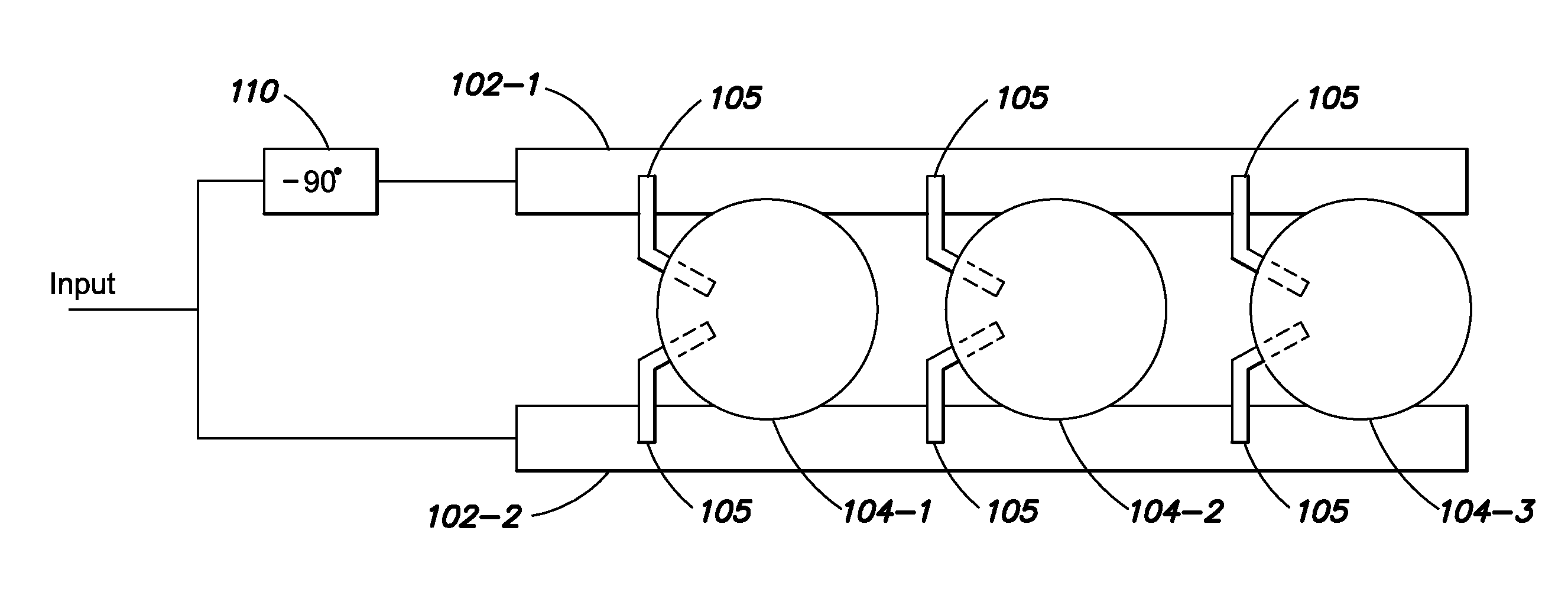
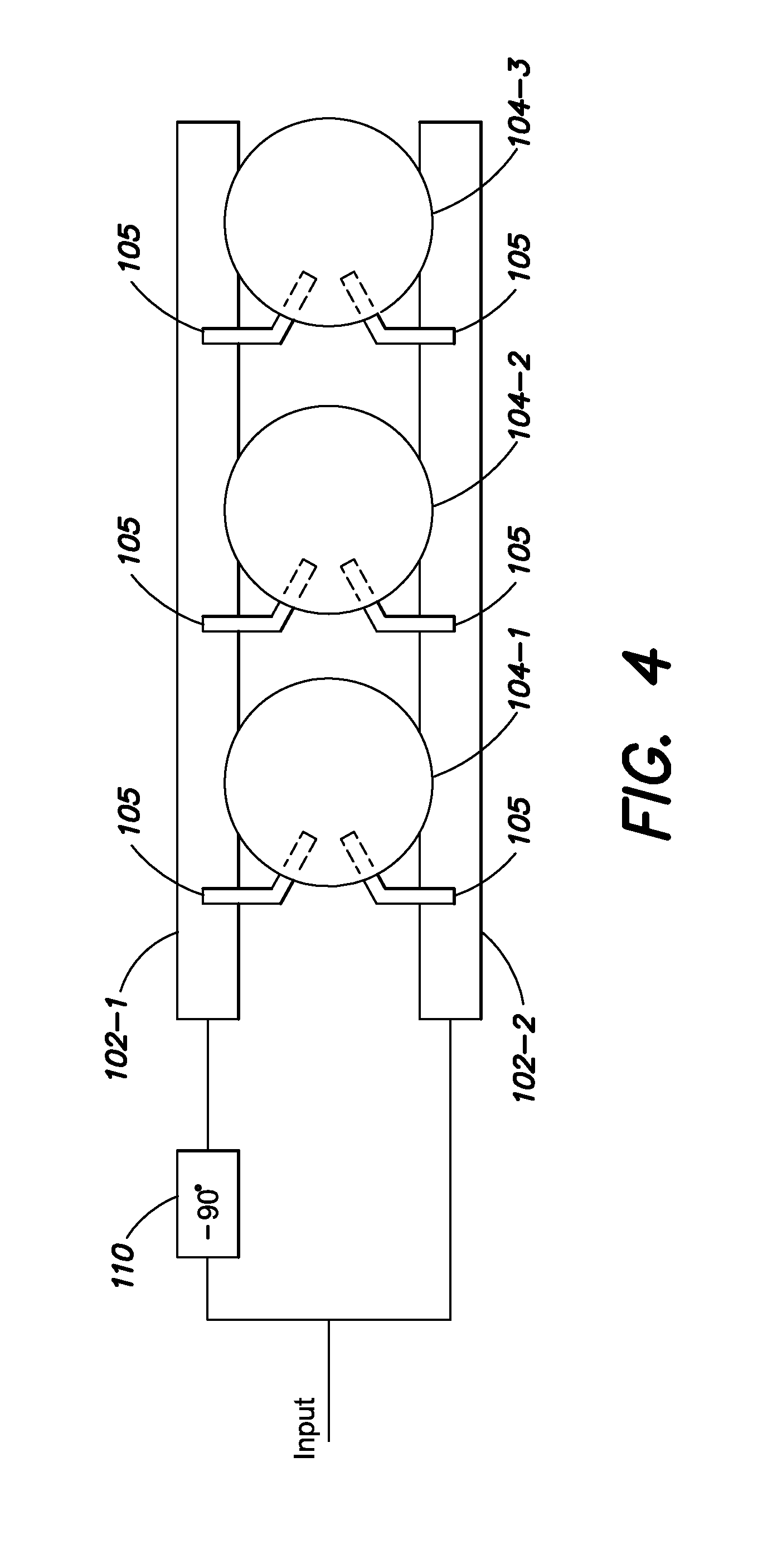
[0040]In a microwave phased array antenna, it is desirable to simplify the design and manufacture of the power dividing phase network. In such components, individual phase controlling elements are placed between each radiating element in series. In this series fed configuration, a transmission line (which may be a waveguide or any other Transverse Electromagnetic Mode (TEM) line) contains all of the antenna element tap points which control power division and sidelobe levels, as well as the phase shifters which control the scan angle of the array. This arrangement provides a savings in the needed electronic circuitry as compared to a parallel feed structure which would typically require many more two-way power dividers to implement the same function.

[0041]By way of introduction, this simplification can be provided by performing the phase shift function by varying the wave propagation velocity of the transmission line, thereby inducing a change in electrical length betw...


PUM


Abstract

Techniques for implementing series-fed antenna arrays with a variable dielectric waveguide. In one implementation, coupling elements with optional controlled phase shifters are placed adjacent each radiating element of the array. To avoid frequency sensitivity of the resulting array, one or more waveguides have a variable propagation constant. The variable waveguide may use certain materials exhibiting this phenomenon, or may have configurable gaps between layers. Plated-through holes and pins can control the gaps; and / or a 2-D circular or a rectangular travelling wave array of scattering elements can be used as well.

Description

CROSS-REFERENCE TO RELATED APPLICATIONS[0001]The present application claims the benefit of U.S. Provisional Patent Application Ser. No. 61 / 772,623, which was filed on Mar. 5, 2013, by John T. Apostolos for a WIDEBAND SCANNING ANTENNA REFINEMENTS USING DIELECTRIC WAVEGUIDES WITH CONFIGURABLE GAPS and is hereby incorporated by reference. It also relates generally to U.S. patent application Ser. No. 13 / 372,117 filed Feb. 13, 2012, which is also incorporated by reference herein.BACKGROUND[0002]1. Technical Field[0003]This patent relates to series-fed phased array antennas and in particular to a coupler disposed between the radiating antenna elements of the array and a waveguide having an adjustable wave propagation constant.[0004]2. Background Art[0005]Phased array antennas have many applications in radio broadcast, military, space, radar, sonar, weather satellite, optical and other communication systems. A phased array is an array of radiating elements where the relative phases of resp...

Claims


Application Information

Patent Timeline
Patent Type & Authority Patents(United States)
IPC IPC(8): H01Q21/06
CPCH01Q21/061H01Q3/2676H01Q21/0043H01Q21/08H01Q11/02H01Q21/068H01Q13/28H01Q21/0068H01Q21/22
Inventor APOSTOLOS, JOHN T.MCMAHON, BENJAMINMOLEN, BRIANFENG, JUDYMOUYOS, WILLIAM
Owner ANTENUM INC
Why Eureka
Try Eureka