
Device and method for generating multi-phase clock pulse signal based on ring oscillator

A multi-phase clock and pulse signal technology, applied in the direction of logic circuit pulse generation, electric pulse generator circuit, power automatic control, etc., can solve the problems of signal accuracy reduction, unstable potential, offset, etc., to avoid circuit The effect of instability

Inactive Publication Date: 2008-08-13
MOAI ELECTRONICS
View PDF2 Cites 6 Cited by
  • Summary
  • Abstract
  • Description
  • Claims
  • Application Information

AI Technical Summary

Problems solved by technology

For example, IEEE Journal of Solid-State Circuits, vol.35, No.11 (November 2000), discloses a 1.3 cycle lock time, non-phase-locked loop / delay locked loop clock multiplier, which is generated by interpolating the clock cycle That is to take the clock pulse (clock on demand), but this method will reduce the accuracy of the signal due to the instability and potential shift caused by the variation of the process parameters of the external capacitor.

Method used


Image

  • Device and method for generating multi-phase clock pulse signal based on ring oscillator
  • Device and method for generating multi-phase clock pulse signal based on ring oscillator
  • Device and method for generating multi-phase clock pulse signal based on ring oscillator

Examples


Embodiment Construction

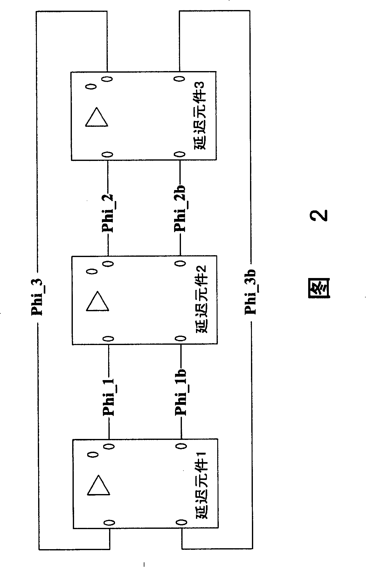
[0020] FIG. 2 is a schematic diagram showing a first embodiment of the present invention, illustrating a ring oscillator generating three-phase clock pulse signals. Referring to FIG. 2, the ring oscillator that can generate 3 phase clock pulse signals includes 3 delay elements (delay element 1-delay element 3), which are connected in series with each other and generate signals Phi_1, Phi_1b, Phi_2, Phi_2b, Phi_3, and Phi_3b , wherein the signals Phi_1b, Phi_2b, and Phi_3b have opposite phases to the signals Phi_1, Phi_2, and Phi_3, respectively. The signals Phi_1, Phi_1b, Phi_2, Phi_2b, Phi_3, and Phi_3b are all non-full swing signals.

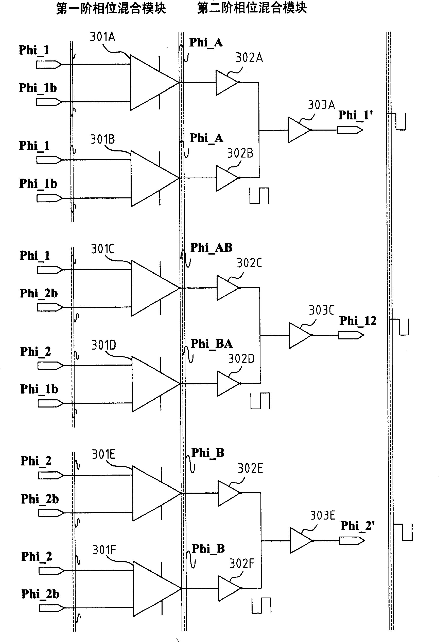
[0021] image 3 Another embodiment of the invention is shown, illustrating a 2-stage phase mixer, which performs phase mixing for 2 input signals of different phases. The 2-stage phase mixer utilizes 2 pairs of non-full swing signals (Phi_1, Phi_2 and their complementary Phi_1b, Phi_2b signals) to generate 3 phase clock signals. The 2-stage...


PUM


Abstract

A device for generating multi-phase clock pulse signal by a ring oscillator and a method thereof are provided. The device comprises: a first level phase mixing module comprising a plurality of differential operation amplifier phase mixing circuits, each of which receives two input signals and one output signal, wherein: the phase of the output signal is interpolated between the two input signals; a second level phase mixing module comprising a plurality of inverter phase mixing circuits, each of which receives two signals output by the fist phase mixing module as the input signal and outputs a clock pulse signal, wherein: the phase thereof is interpolated between two signals output by the first level phase mixing module. The method of the invention comprises the following steps of: using a ring oscillator to supply at least two non-complete vibrating signals; using the differential operation amplifier phase mixing circuit to mix the phase of the two non-complete vibrating signals generated by the ring oscillator; and using the inverter phase mixing circuit to generate the multi-phase pulse signal with interpolation phase.

Description

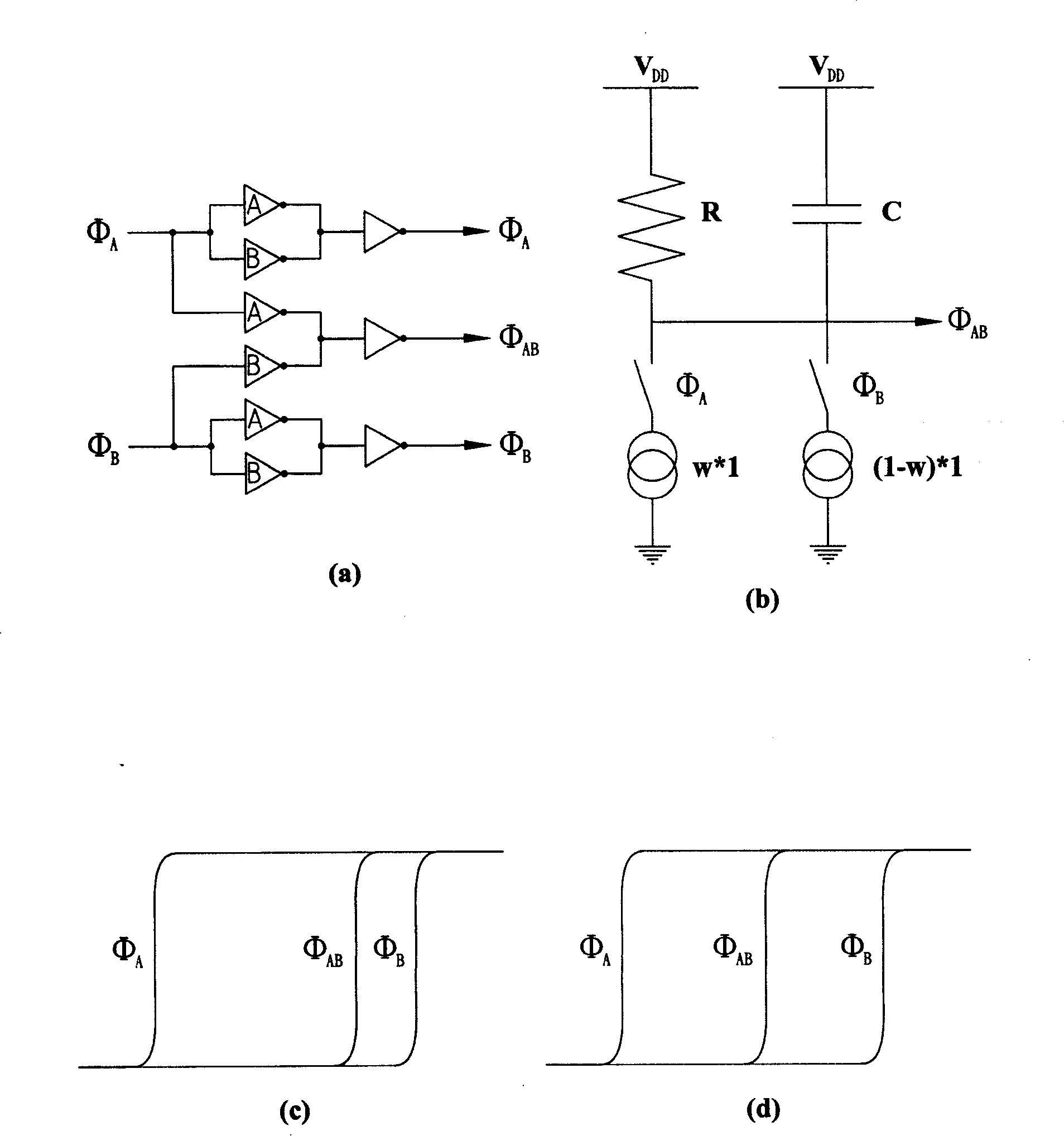
technical field [0001] The present invention relates to a high-frequency multi-phase ring oscillator, especially a new device and method for generating a high-frequency multi-phase oscillator by means of interpolation of non-full swing signals. Background technique [0002] A multi-phase oscillator (MPO) plays an important role in many data transmission applications, and many methods have been proposed to realize the multi-phase oscillator circuit. For example, a ring oscillator is an oscillator with an odd number of inverters connected in series. Because the odd number of levels is connected in series, the output signal of the inverter will be at a high level. (high) / low (low) oscillation. However, the traditional ring oscillator configuration can only generate an odd number of multi-phase signals; another problem with the ring oscillator is that too many inverters are connected in series in the ring oscillator, which will make it impossible to obtain High frequency oscil...

Claims


Application Information

Patent Timeline
IPC IPC(8): H03K3/03H03L7/00
Inventor 王铭鸿林鹏飞林铭琦
Owner MOAI ELECTRONICS
Learn More