Electronic industrial motor operator control system

a control system and industrial motor technology, applied in the direction of electric programme control, motor/generator/converter stopper, dynamo-electric converter control, etc., can solve the problems of wreaking all kinds of logic mayhem, microprocessor reliability disadvantages, and lack of prior art utilizing three button stations in any motor operator or industrial type of motor operator. to achieve the effect of improving reliability and improving accuracy

Inactive Publication Date: 2005-08-11
MECHANICAL INGENUITY CORP
View PDF22 Cites 6 Cited by
  • Summary
  • Abstract
  • Description
  • Claims
  • Application Information

AI Technical Summary

Benefits of technology

[0022] This invention discloses an electronic control system for an Industrial Motor Operator that uses standard steady state logic to improve reliability in rough service wet and dirty environments. It includes means of providing electronic snow limit to close limit sensing removing the need for two switches and radically improving its accuracy. A low voltage switch reverses the high voltage motor wires and at the same time reverses the open limit, close limit, and snow limit sensors mechanical positions. It discloses a system using lamps to indicate that the power wiring is connecting to three-phase motors in the correct sequence or that single-phase motors have their windings correctly phased.

Problems solved by technology

Pertinent patent office art utilizing three button stations in any motor operator or prior art on industrial types of motor operators seem to be lacking.
Microprocessors have some reliability disadvantages in a simple control system, most notably a high frequency clock, and stored software programming requiring some kind of non-volatile memory.
The exception is low voltages at high frequencies wherein moisture conducts the oscillating signal over to adjacent lines causing corrosion and wreaking all kinds of logic mayhem.
A clock signal is susceptible to having its transitions deformed by moisture, electrical noise and double or missing clocks occur.
Automobile designers place microprocessors inside a watertight enclosure and that is part of its associated overhead cost.
Losing one-bit of flip-flop storage during a power outage can mean that the direction of travel is uncertain.
Battery backup solves this problem but adds significant cost and once the battery wears out, a dangerous situation develops.
Industrial motor operators command hundreds or even thousands of pounds of force and uncertainty about their direction of movement is bad.
Microprocessors use software but also require substantial hardwired logic to interconnect external support items such as power supplies, memory, data busses, noise filters and power components such as relays.
However, the recent arrival of automatic insertion equipment capable of placing microscopically small components at a 300-per-minute rate makes such labor advantages moot.

Method used


Image

  • Electronic industrial motor operator control system
  • Electronic industrial motor operator control system

Examples


Embodiment Construction

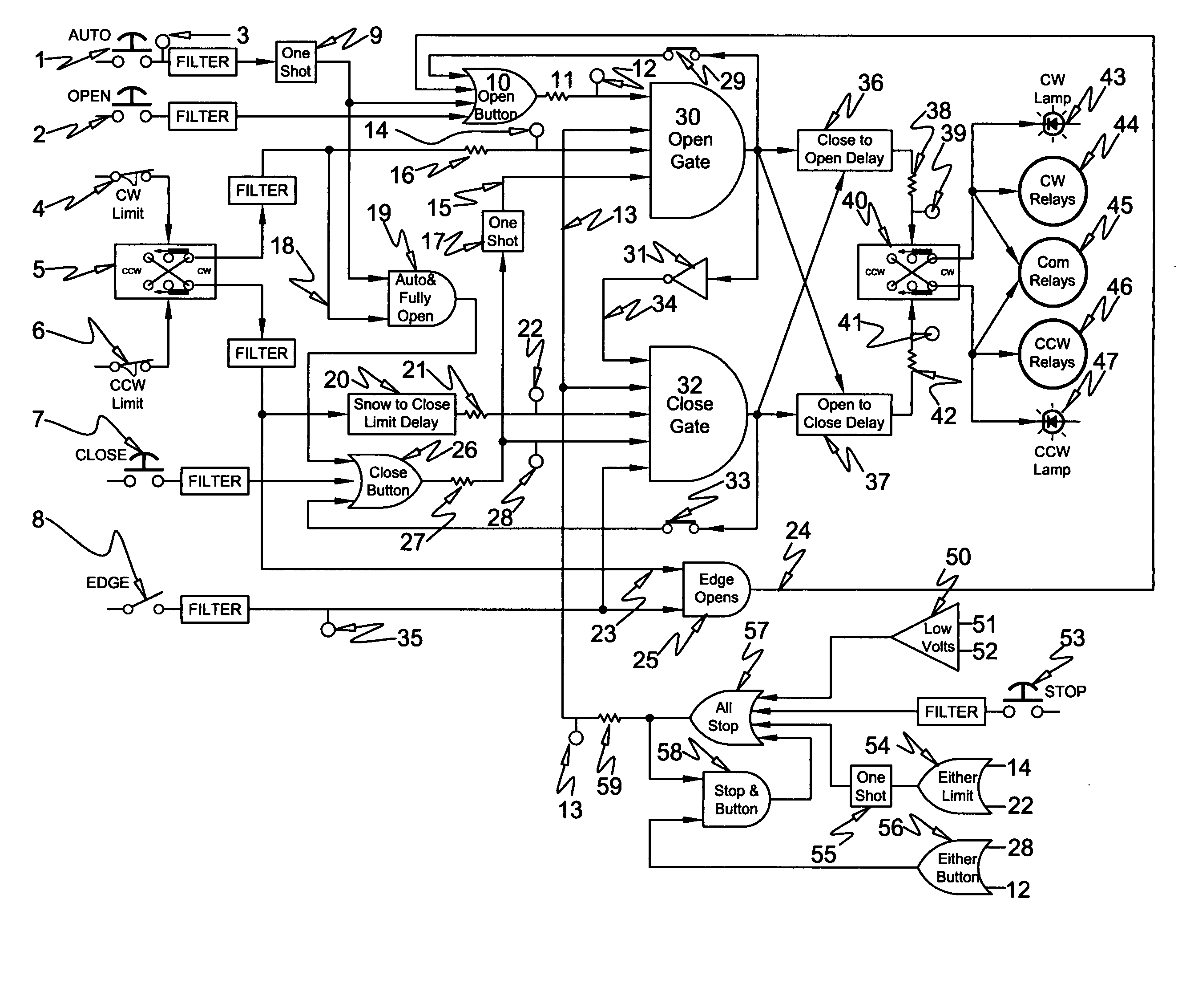
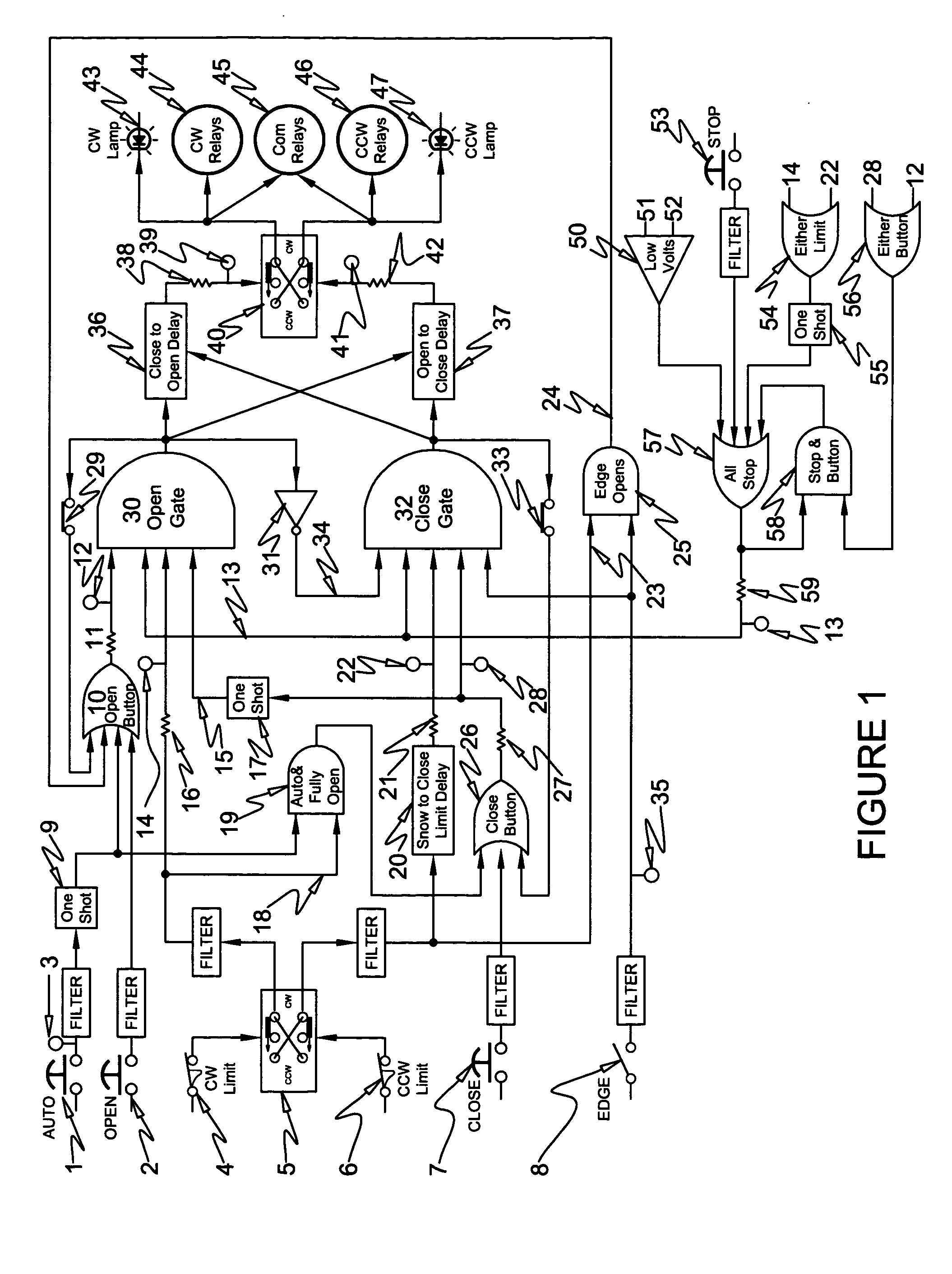
[0026] The Open-Button gate 10, of FIG. 1, reacts to Open-Pushbutton 2 or any other open signal (logical OR) by driving resistor 11 to input 12 of the Open-Gate 30. The output of Open-Gate 30 connects to slide switch 29, feeding back into the Open-Button gate 10 thereby latching both gates. Once latched, both gates remain latched even after releasing Open-Pushbutton 2. Removing any other input signal from Open-Gate 30, such as, stop signal 13, or limit switch signal 14, or the I-shot signal 15 will disable gate 30 and unlatch its output. Open-Gate 30 remains off and disabled until the return of all its input signals (logical AND). Disconnecting slide switch 29, removes the abovementioned feedback latching command such that constant pressing of Open-Pushbutton 2 is required to maintain an output signal from Open-Gate 30. A constant open command at 12 cannot produce an output signal from Open-Gate 30 unless signals 13, 14, and 15 are continuously present. In this manner, slide switch ...


PUM


Abstract

This invention discloses an electronic control system for an Industrial Motor Operator that uses standard steady state logic to improve reliability in rough service wet and dirty environments. It includes means of providing electronic snow limit to close limit sensing removing the need for two switches and radically improving its accuracy. A low voltage switch reverses the high voltage motor wires and at the same time reverses the open limit, close limit, and snow limit sensors mechanical positions. It discloses a system using lamps to indicate that the power wiring is connecting to three-phase motors in the correct sequence or that single-phase motors have their windings correctly phased.

Description

BACKGROUND OF THE INVENTION [0001] Industrial door / gate motor operators distinguish themselves from residential garage door operators by using three pushbuttons, open, close, and stop. Called a three-button station their operation would seem to be obvious but there are variations. Automatic operation, termed “momentary”, requires just a momentary press of the open or close button to move the motor operator to its limit of travel. Momentary operation requires a safety device such as a safety edge or photo-eye so as not to crush something in the opening. Non-Automatic operation, termed “constant”, requires constant pressure on a pushbutton to move the motor operator to its limit of travel. Constant operation requires that all three-button stations be next to the entryway and that releasing the pushbutton will immediately stop the operator. Further distinction between residential and industrial motor operators is that of output torque, industrial operators are those that exceed 100-lbs...

Claims


Application Information

Patent Timeline
Patent Type & Authority Applications(United States)
IPC IPC(8): G05B19/07H02P1/00H02P1/22H02P3/00
CPCG05B19/07G05B2219/37627E05Y2800/748E05Y2400/57G05B2219/45242
Inventor BECKERMAN, HOWARD
Owner MECHANICAL INGENUITY CORP
Why Eureka
Try Eureka