System and method of producing a null free oblong azimuth pattern with a vertically polarized traveling wave antenna

a traveling wave antenna and null free technology, applied in the field of radio frequency electromagnetic signal broadcast antennas, can solve the problems of limited beam tilt capability, unidirectional panels, and limited knowledge of antennas for providing such patterns, and achieve the effect of moderate power capability and simple mechanical construction

Inactive Publication Date: 2008-04-03
SPX CORP
View PDF1 Cites 7 Cited by
  • Summary
  • Abstract
  • Description
  • Claims
  • Application Information

AI Technical Summary

Benefits of technology

[0012]The foregoing disadvantages are overcome, to a great extent, by the invention, wherein in one aspect a vertically polarized traveling wave antenna is provided that in some embodiments of the invention affords simplicity in mechanical construction, reduced

Problems solved by technology

The shortcomings of a vertically polarized collinear dipole antenna include limited capacity to realize beam tilt.
The known antennas for providing such patterns are largely limited to the above-referenced panel radiators and arrays thereof.
Such panels are effectively unidirectional, with a single beam having breadth that depends on the intrinsic gain of the individual panel, increasingly narrow as the number of cofiring panels in an array increases.
This produces deep nulls to the sides, which are potentially unacceptable for mobile coverage, and may necessi

Method used


Image

  • System and method of producing a null free oblong azimuth pattern with a vertically polarized traveling wave antenna
  • System and method of producing a null free oblong azimuth pattern with a vertically polarized traveling wave antenna
  • System and method of producing a null free oblong azimuth pattern with a vertically polarized traveling wave antenna

Examples


Embodiment Construction

[0037]The invention will now be described with reference to the drawing figures, in which like reference numerals refer to like parts throughout. The invention provides an apparatus and method that in some embodiments provides an antenna that supports a substantially single-axis, null-free, vertically-polarized propagation pattern with high gain and moderate power handling capability.

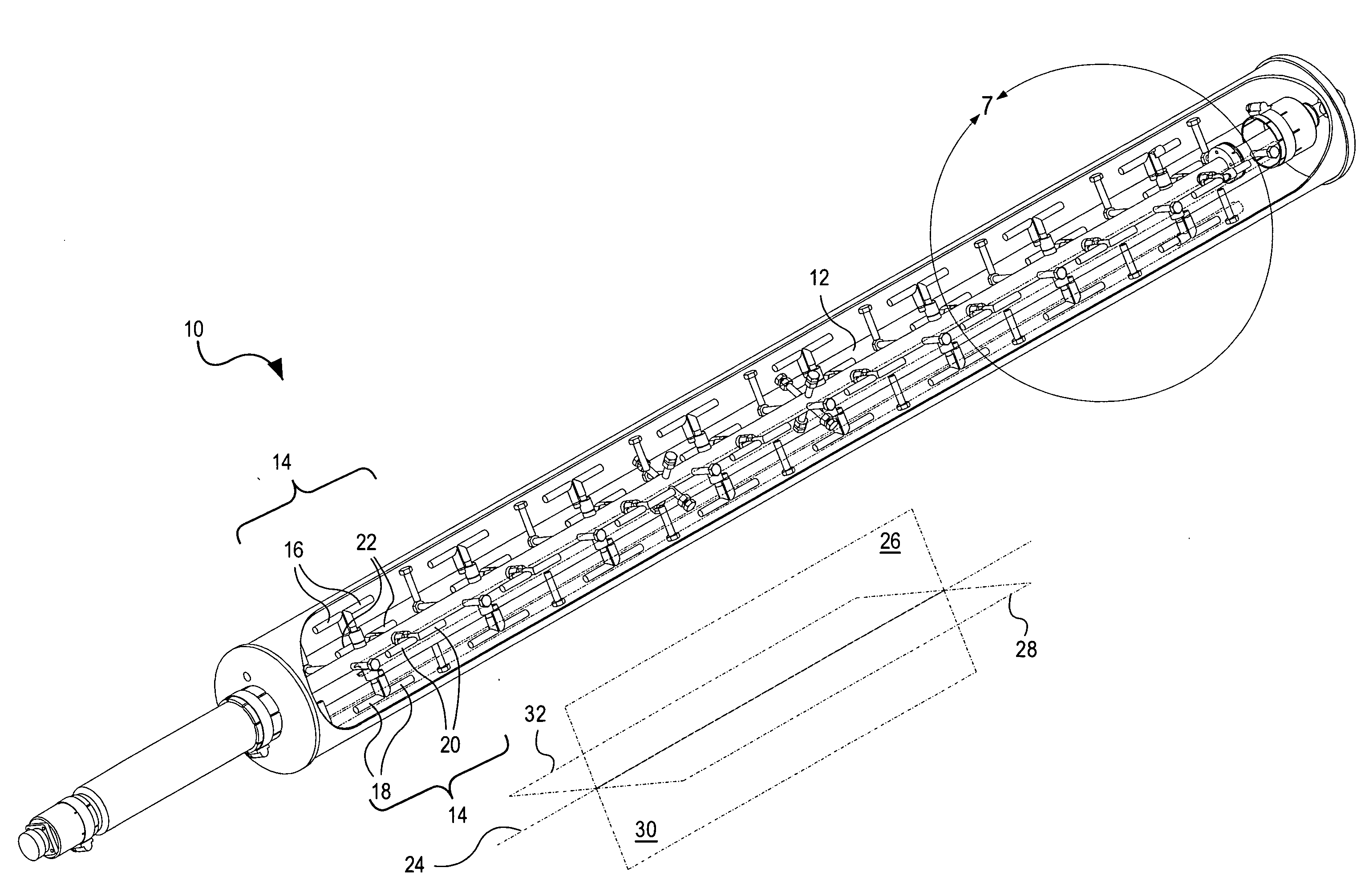
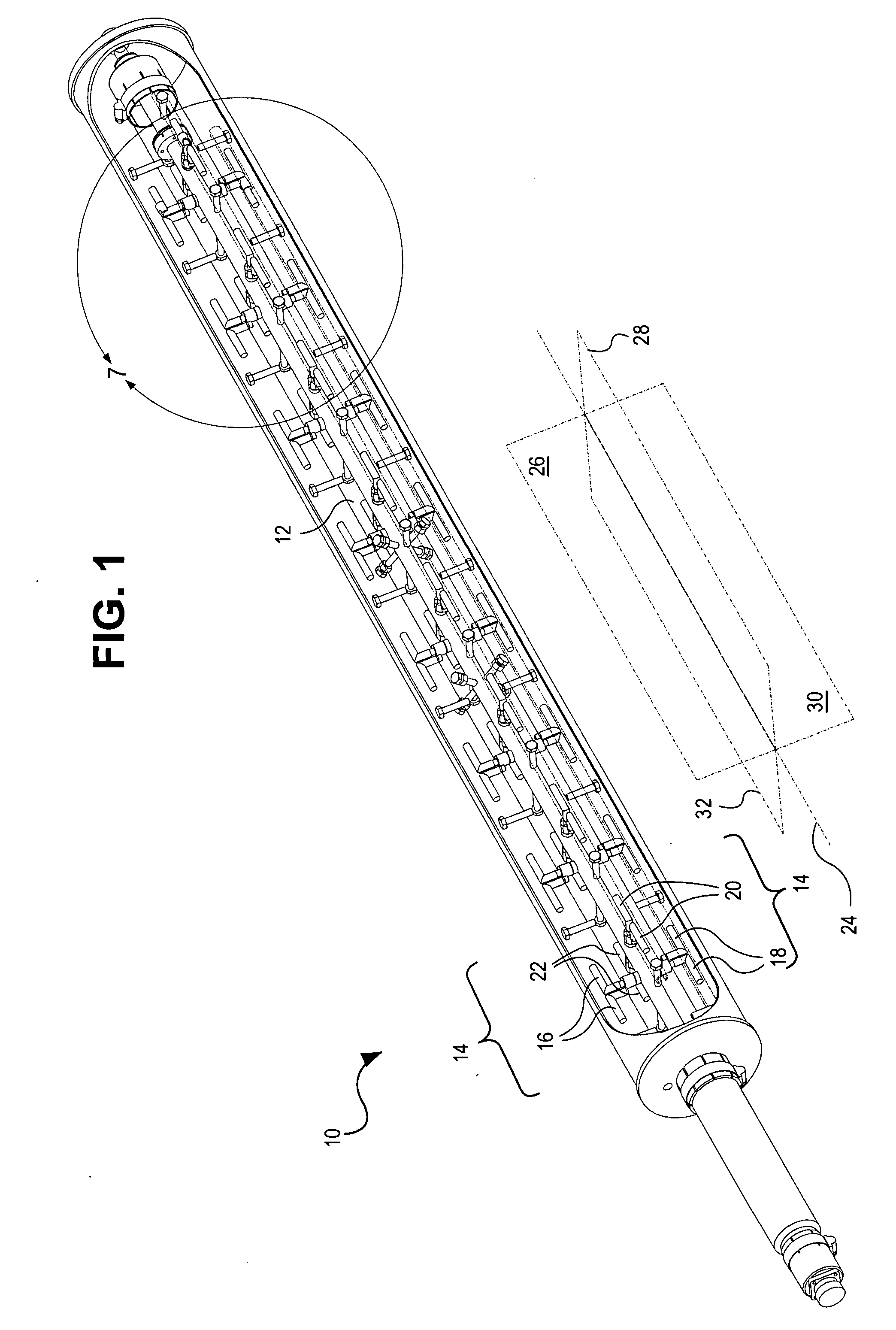
[0038]FIG. 1 shows a multiple-bay antenna 10 according to one embodiment of the invention. The antenna 10 uses a self-supporting, vertical, straight coaxial line (coax) 12 to couple a signal between a feed line and multiple radiating elements in the form of a traveling wave. At each bay 14, a first dipole 16 and a second dipole 18 are positioned on opposite sides of the coax 12, with the second dipole 18 inverted with respect to the first dipole 16, so that the polarities of the radiated signals are opposite. It is noted that the cylindrical and effectively grounded outer conductor of the coax 12 is int...


PUM


Abstract

A vertically polarized traveling wave antenna forms peanut-type directional lobes without significant nulls between the lobes. A self-supporting coaxial line feeds quad-dipole bays coupled around the coaxial line, with opposed dipole pairs spaced along the coaxial line. Matched-layer spacing provides substantial cancellation of the reactive components of the loads. Dipoles are oriented parallel to the coaxial line axis, with opposite “hot” (center coupled) elements oppositely oriented. Radiated signals have rotating phase. Changing the spacing within quads from a quarter wavelength or rotating the second dipole pair of each quad away from a right angle causes the antenna to radiate strongly on one axis and weakly at right angles thereto, without the nulls of back-to-back panel antennas.

Description

RELATED APPLICATIONS[0001]This application is a continuation-in-part of U.S. nonprovisional patent application Ser. No. 11 / 499,644 (“the '644 application”), titled, “Vertically Polarized Traveling Wave Antenna System and Method”, filed Aug. 7, 2006, which is hereby incorporated by reference in its entirety.FIELD OF THE INVENTION[0002]The present invention relates generally to radio frequency (RF) electromagnetic signal broadcast antennas. More particularly, the present invention relates to traveling-wave linear array transmitting antennas.BACKGROUND OF THE INVENTION[0003]There has recently been an industry focus on digital streaming of content to mobile, portable, and handheld receivers through terrestrial broadcast systems. This type of broadcasting is being developed for implementation in licensed UHF frequency bands such as 0.7 GHz to 1.0 GHz (upper L-Band: TV channels 52 and above; mobile radio) and 1 GHz to 2 GHz (lower S-band).[0004]At L-Band frequencies, the preferred method ...

Claims


Application Information

Patent Timeline
IPC IPC(8): H01Q21/00H01Q9/18
CPCH01Q1/246H01Q3/26H01Q21/205H01Q21/14H01Q21/0037
Inventor SCHADLER, JOHN L.SKALINA, ANDRE
Owner SPX CORP
Why Eureka
Try Eureka