
Integrated substrate gap waveguide circularly polarized slot traveling wave array antenna

A technology of gap waveguide and integrated substrate is applied in the field of integrated substrate gap waveguide circularly polarized slot traveling wave array antenna, which can solve the problems of weak electromagnetic shielding performance and complex structure of circularly polarized antenna, and achieve strong anti-interference ability. , low sidelobe, easy to integrate effect

Pending Publication Date: 2019-06-28
YUNNAN UNIV
View PDF8 Cites 6 Cited by
  • Summary
  • Abstract
  • Description
  • Claims
  • Application Information

AI Technical Summary

Problems solved by technology

[0006] The technical problem mainly solved by the present invention is to provide an integrated substrate gap waveguide circularly polarized slot traveling wave array antenna, which can overcome the shortcomings of the existing circularly polarized antennas such as complex structure and weak electromagnetic shielding performance

Method used


Image

  • Integrated substrate gap waveguide circularly polarized slot traveling wave array antenna
  • Integrated substrate gap waveguide circularly polarized slot traveling wave array antenna
  • Integrated substrate gap waveguide circularly polarized slot traveling wave array antenna

Examples


Embodiment Construction

[0027] The technical solutions in the embodiments of the present invention will be clearly and completely described below in conjunction with the accompanying drawings in the embodiments of the present invention. Obviously, the described embodiments are only a part of the embodiments of the present invention, rather than all the embodiments. Based on the embodiments of the present invention, all other embodiments obtained by those of ordinary skill in the art without creative work shall fall within the protection scope of the present invention.

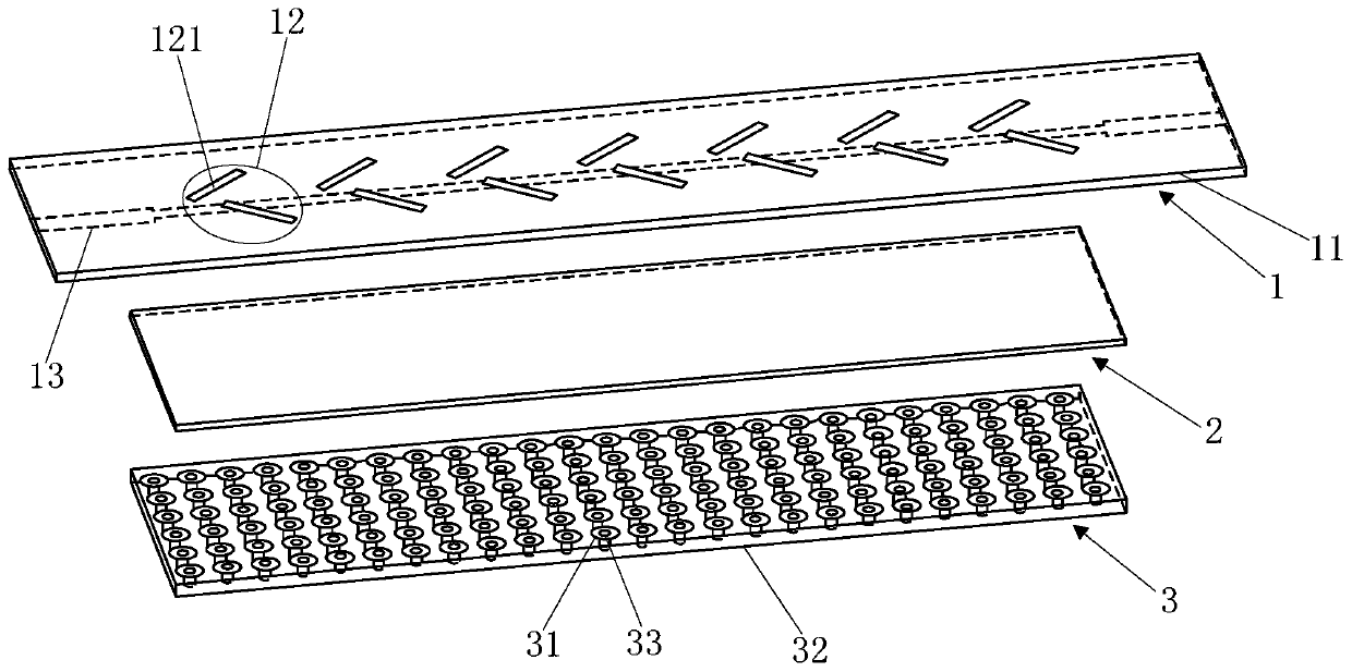
[0028] Refer to Figure 1 to Figure 5 The integrated substrate gap waveguide circular polarization slot traveling wave array antenna of the embodiment of the present invention includes an upper dielectric plate 1, a lower dielectric plate 3, and a spacer dielectric plate 2 arranged between the upper dielectric plate 1 and the lower dielectric plate 3.

[0029] The upper surface of the upper dielectric board 1 is printed with a first copper-...


PUM


Abstract

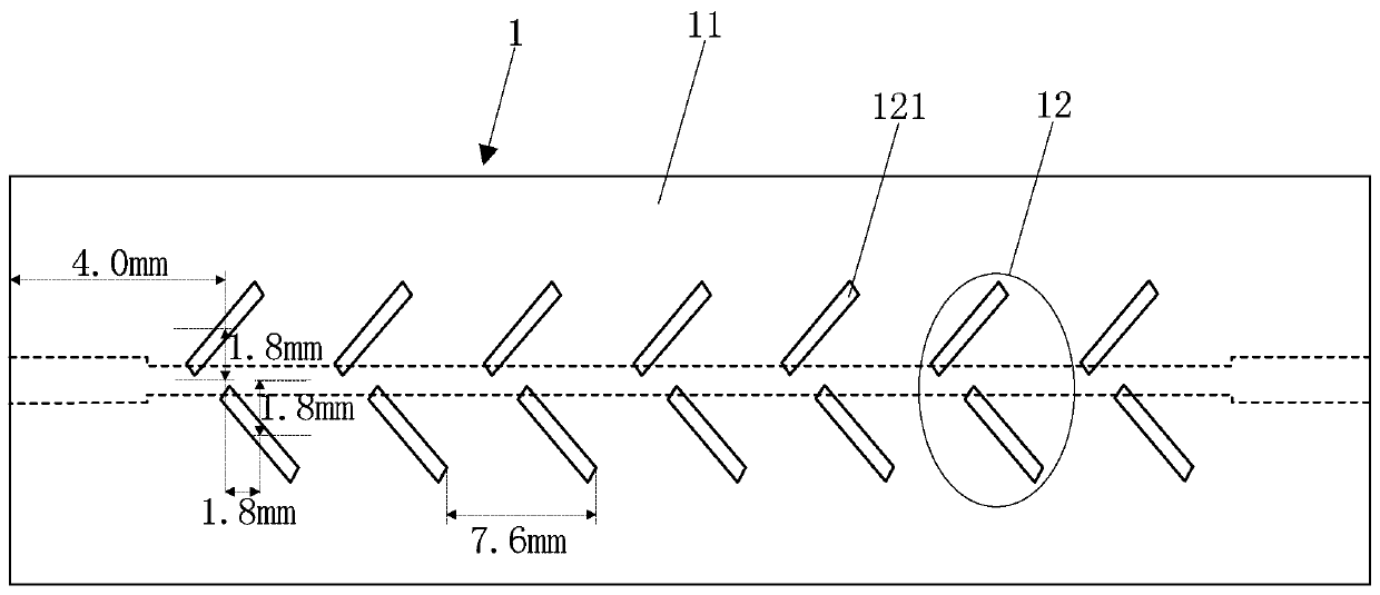
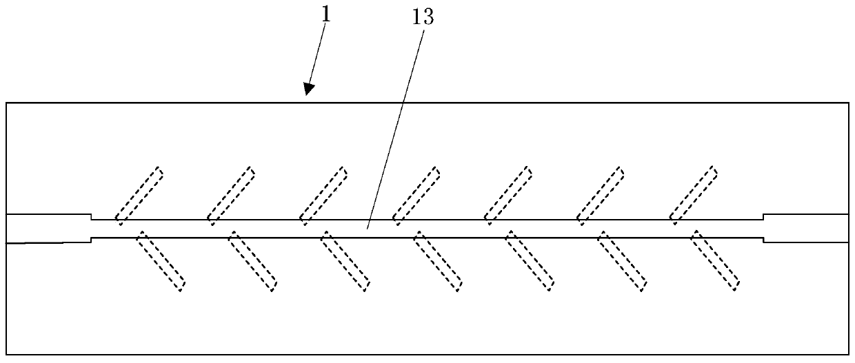
The invention discloses an integrated substrate gap waveguide circularly polarized slot traveling wave array antenna which comprises an upper dielectric plate, a lower dielectric plate and a spacer dielectric plate disposed between the upper dielectric plate and the lower dielectric plate. A first copper cladding layer is printed on an upper surface of the upper dielectric plate, a plurality of slit units spaced apart in a predetermined direction are etched on the first copper cladding layer, and each of the slit units comprises two rectangular slits whose length directions intersect and are not parallel to the predetermined direction, and a feeding microstrip line arranged in the predetermined direction is printed on a lower surface of the upper dielectric plate. Circular metal patches which are periodically arranged are printed on an upper surface of the lower dielectric plate, a second copper cladding layer is printed on a lower surface of the lower dielectric plate, each of the circular metal patches is provided with a metal through hole which passes through the lower dielectric plate, and the metal through hole is connected to the second copper cladding layer. According to theinvention, the disadvantages of complex structure and weak electromagnetic shielding performance of an existing circularly polarized traveling wave antenna can be overcome.

Description

Technical field [0001] The present invention relates to the field of antenna technology, in particular to an integrated substrate gap waveguide circular polarization slot traveling wave array antenna. Background technique [0002] Because of its good compatibility and good anti-interference ability, circularly polarized antennas are widely used in scenarios such as navigation satellites, radars, and mobile communications. So far, circularly polarized antennas working in the millimeter wave band can be roughly divided into microstrip circularly polarized antennas, metal rectangular waveguide (RW) circularly polarized antennas, and substrate integrated waveguide (SIW) circularly polarized antennas. However, in the face of millimeter wave band applications, traditional circularly polarized antennas have some problems. For example, pure metal structures are difficult to manufacture in the millimeter wave band, and the electromagnetic shielding performance of the substrate integrated ...

Claims


Application Information

Patent Timeline
Patent Type & Authority Applications(China)
IPC IPC(8): H01Q1/38H01Q1/36H01Q1/50H01Q13/10H01Q21/06
Inventor 申东娅王艺安
Owner YUNNAN UNIV
Learn More