Traveling wave antenna for electromagnetic heating

a traveling wave and electromagnetic heating technology, applied in the field of radio frequency antennas, can solve the problems of reducing the amount of power delivered by the rf antenna, increasing the losses and/or heating in the transmission line and the rf generator, and reducing the overall system efficiency

Active Publication Date: 2017-08-10
ACCELEWARE
View PDF4 Cites 6 Cited by
  • Summary
  • Abstract
  • Description
  • Claims
  • Application Information

AI Technical Summary

Benefits of technology

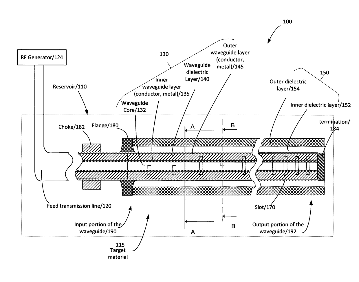
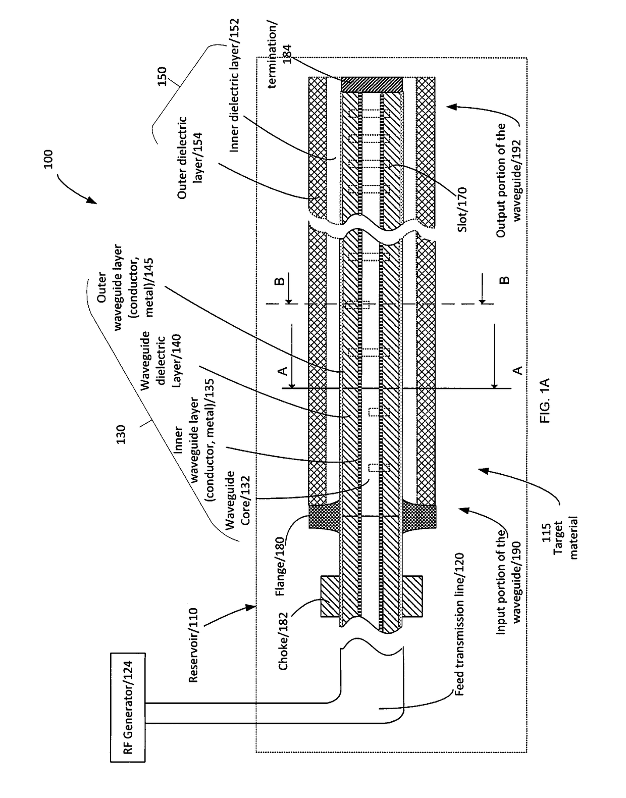
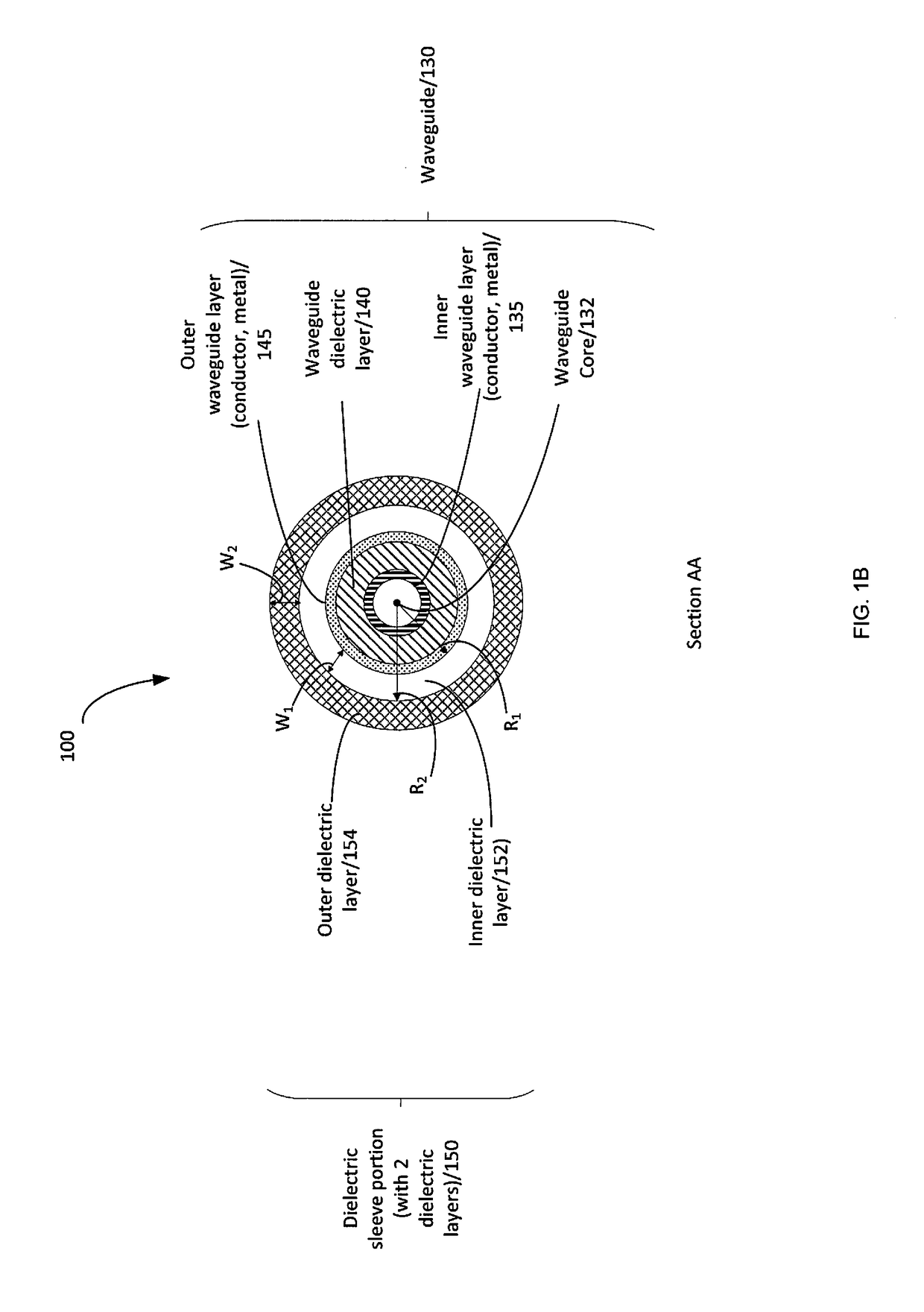
[0006]In a first aspect, there is provided a radio frequency antenna for radiating electromagnetic energy into a reservoir filled with a target material, the antenna being operatively connected to a feed transmission line. In at least one embodiment, the antenna may include a waveguide having an inner waveguide layer a waveguide dielectric layer, and an outer waveguide layer; at least one slot formed in the outer waveguide layer, the at least one slot being adapted to radiate the electro-magnetic energy into the reservoir; and a sle

Problems solved by technology

This EM power reflection reduces the amount of power delivered by the RF antenna to the target material in the reservoir and increases losses and/or heating in the transmission line and the RF generator.
This typically leads to a decrease in the overall system effi

Method used


Image

  • Traveling wave antenna for electromagnetic heating
  • Traveling wave antenna for electromagnetic heating
  • Traveling wave antenna for electromagnetic heating

Examples


Embodiment Construction

[0039]Numerous embodiments are described in this application, and are presented for illustrative purposes only. The described embodiments are not intended to be limiting in any sense. The invention is widely applicable to numerous embodiments, as is readily apparent from the disclosure herein. Those skilled in the art will recognize that the present invention may be practiced with modification and alteration without departing from the teachings disclosed herein. Although particular features of the present invention may be described with reference to one or more particular embodiments or figures it should be understood that such features are not limited to usage in the one or more particular embodiments or FIGS. with reference to which they are described.

[0040]The terms “an embodiment”, “embodiment”, “embodiments”, “the embodiment”, “the embodiments”, “one or more embodiments”, “some embodiments”, and “one embodiment” mean “one or more (but not all) embodiments of the present inventi...


PUM


Abstract

A radio frequency antenna for radiating electromagnetic energy into a reservoir filled with a target material, the antenna being operatively connected to a feed transmission line. The antenna includes a waveguide, at least one slot formed in the outer waveguide layer, and a sleeve portion enclosing at least a portion of the waveguide. The sleeve portion comprises at least first and second dielectric layers where the permittivity of the second dielectric layer is higher than the permittivity of the first dielectric layer and the first dielectric layer is positioned in closer proximity to the waveguide than the second dielectric layer. When the antenna is inserted into the reservoir, the input impedance of the antenna remains matched to the feed transmission line for a wide range of target materials.

Description

FIELD[0001]The embodiments described herein relate to radio frequency antenna for radiating electromagnetic energy into a reservoir filled with a target material such as hydrocarbons.BACKGROUND OF THE INVENTION[0002]Radio-frequency (RF) antennas may be used in various applications where it is desired to radiate electromagnetic (EM) energy into a reservoir filled with a target material in order to change one or more of the target material's characteristics. For example, radiation of EM energy may initiate or enhance a chemical process or reaction, heat the target material, or help to perform an analysis of the target material's physical properties or composition. EM radiation may be used at different stages of oil production: heating the soil to decrease viscosity of oil, improve oil's mobility, or upgrade the bitumen or heavy oil in a process on the surface or underground.[0003]The RF antenna and its environment form a connected system, and the RF antenna's performance greatly depen...

Claims


Application Information

Patent Timeline
IPC IPC(8): H05B6/72E21B43/24H01Q13/12H05B6/70H01Q13/10H01Q1/36
CPCH05B6/72H01Q13/103E21B43/2401H01Q13/12H05B6/708H01Q1/362H01Q21/0043H05B6/802
Inventor OKONIEWSKI, MICHAL M.PASALIC, DAMIR
Owner ACCELEWARE
Why Eureka
Try Eureka