Method for manufacturing a seismic cable

a manufacturing method and cable technology, applied in seismology, seismology, instruments, etc., can solve the problems of severe noise to the signals and insufficient techniques

Inactive Publication Date: 2000-02-01
WESTERNGECO LLC
View PDF13 Cites 64 Cited by
  • Summary
  • Abstract
  • Description
  • Claims
  • Application Information

AI Technical Summary

Problems solved by technology

The in-line receiver is not affected but the cable-rolling motion introduces severe noise to the signals originating from the cross-line and the vertically-polarized receivers.
Although several mathematical data-processing techniques are known for reducing signal distortion due to poor ground coupl

Method used


Image

  • Method for manufacturing a seismic cable
  • Method for manufacturing a seismic cable
  • Method for manufacturing a seismic cable

Examples


Embodiment Construction

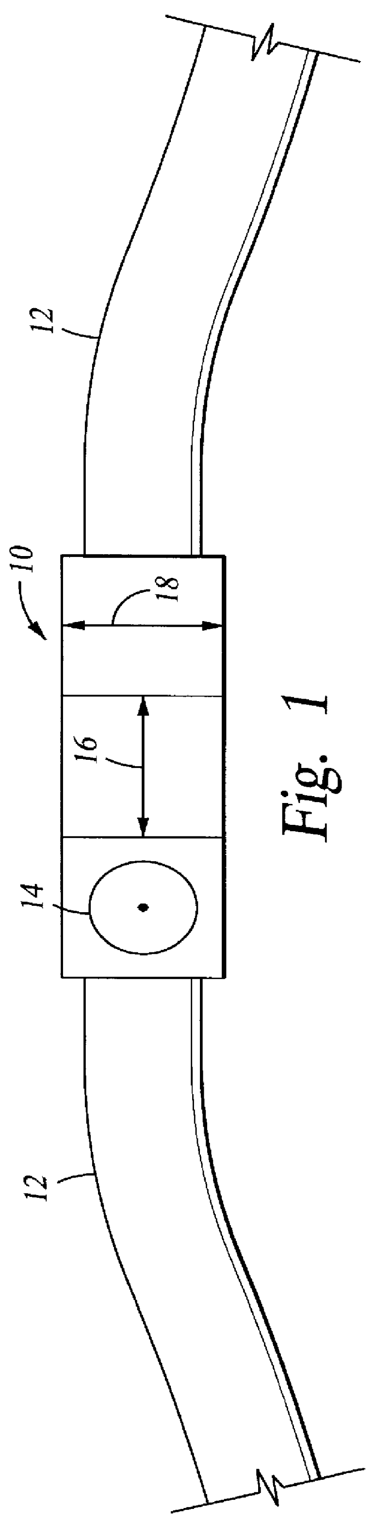
FIGS. 1-4 are not to scale. FIG. 1 is a schematic side view of a three-axis receiver 10 secured to an ocean bottom cable (OBC) 12. A multi-axis receiver 10 of any well-known type, includes a cross-line motion-responsive axis 14, in-line motion-responsive axis 16, and a vertical motion-responsive axis 18, all mounted on gimbals in a single case. This invention may be applied to either land or marine operations but for purposes of example only and not by way of limitation, this disclosure will be discussed in terms of an OBC.

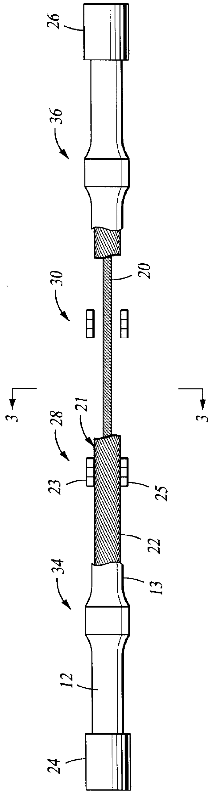
FIG. 2 is a top view of an OBC section 12 with a portion of a fluid-impermeable protective sheath 13 cut away to show the internal construction. An OBC section may be manufactured by providing a stress member, 20 of any desired type. Signal communication channels such as electrical wire lines or optical fibers, generally shown as 22 are associated with the stress member 20, such as by wrapping as shown, to form a cable carcass 21. Each end of OBC 12 is anchored to...


PUM


Abstract

Ocean bottom seismic cables are subject to rolling motions due to seismic wave fields and current action which cause poor receiver ground-coupling and signal distortion, particularly along the cross-line and vertical axes. Two multi-axial receivers are mounted on opposite sides of the cable in a single cluster. When the cable rolls, the axial response of one receiver of the cluster cancels the axial response of the other receiver of that cluster.

Description

1. Field of the InventionThis is a method for manufacturing a cable for use in seismic exploration. The cable is designed to include along its length, spaced-apart clusters of multi-axis geophones. Each cluster includes at least two multi-axis geophones that are secured to opposite sides of the cable. Seismic signals resulting solely from cable rotation about its in-line axis, are expected to cancel.2. Discussion of Relevant ArtAs is well known to geophysicists, in the conduct of a seismic survey, a sound source, at or near the surface of the earth, is caused periodically to inject an acoustic wavefield into the earth at each of a plurality of regularly-spaced survey stations. The wavefield radiates in all directions to insonify the subsurface earth formations whence it is reflected back to be received by seismic sensors (receivers) located at designated stations at or near the surface of the earth. The seismic sensors convert the mechanical earth motions, due to the reflected wavef...

Claims


Application Information

Patent Timeline
IPC IPC(8): G01V1/16G01V1/20G01V1/38
CPCG01V1/201G01V1/3817
Inventor GAISER, JAMES E.
Owner WESTERNGECO LLC
Why Eureka
Try Eureka