Zoom lens

a zoom lens and zoom technology, applied in the field of zoom lenses, can solve the problems of difficult to keep the optical performance at a high level, difficult to suppress the variation of aberrations with zooming to a minimum, and the size of the lens system is rapidly increased

Inactive Publication Date: 2000-02-22
CANON KK
View PDF18 Cites 28 Cited by
  • Summary
  • Abstract
  • Description
  • Claims
  • Application Information

AI Technical Summary

Benefits of technology

Another object of the invention is to provide a wide-angle high range zoom lens employing the "rear" focusing method. As the zooming movements of the lens groups and the paraxial refractive power arrangements are made appropriate, good stability of optical performance is maintained against zooming from the wide-angle end to the telephoto end, or throughout the entire zooming range, and against focusing to suit from infinity to the minimum object distance, or throughout the entire focusing range.

Problems solved by technology

If the 2-group type is applied to form a zoom lens of too much increased range, the lens system suffers from a rapid increase of the size.
Moreover, it becomes difficult to keep the optical performance at a high level.
For the range to increase, therefore, it becomes difficult to suppress the variation of aberrations with zooming to a minimum.
If the refractive power arrangement of the lens groups and their forms are inappropriate, the variation of aberrations with zooming increases so greatly that good stability of high optical performance is hardly maintained throughout the entire zooming range, no matter how many constituent lenses may be used.
If the aspheric surface is not introduced into the appropriate lens surface, effective correction of aberrations becomes difficult to do.
So, it becomes difficult for this aspheric surface to correct these aberrations simultaneously.
Thus, a long bulky lens system results.
Moreover, as the refractive power of each of the lens groups is strengthened, the range of variation of aberrations increases, which is difficult to correct well by that aspheric surface.
However, the total number of constituent lenses is too large and the aspheric surface does not effect sufficient results.
However, the second group has a large number of lens elements and the aspheric surface in the same lens group does not sufficiently contribute to improvements of the compact form.
Moreover. if a further widening of the maximum angle of field is done, good correction of aberrations is difficult to perform over the entire zooming range.
Thus, the aberrations which would come to be a problem when the maximum angle of field widens and the zooming range increases are corrected well.
This makes it easy to secure the back focal distance, which would otherwise become a problem when widening the maximum angle of field.
If this approach to the improvement of the compact form and the increase of the range is pushed, the difficulty of correcting the positive Lens groups for spherical aberration of the negative direction increases rapidly.
When these conditions are violated, good correction of on-axial aberrations becomes difficult to do so effectively as not to greatly affect off-axial aberrations over the entire zooming range.
By this, it is made easier to secure the back focal distance, which becomes a problem when to widen the angle of field.
Otherwise, the corner illumination could not be secured at a satisfactory level.
This increases the total length of the entire lens system objectionably.
So, the total length of the complete lens increases objectionably.
Moreover, the first lens group L1 produces strong spherical aberration as is over-corrected, which is difficult to correct by any design of the other lens groups.
When the lower limit is exceeded, it becomes difficult to secure the predetermined value of the back focal distance.
Therefore, the predetermined value of the back focal distance is hardly secured.
As a result, the total length of the complete lens increases objectionably.
Therefore, the size of the entire lens system is difficult to minimize.
When the lower limit is exceeded, it becomes difficult to secure the predetermined value of the back focal distance in the wide-angle end.
As a result, the third lens group L3 gets an objectionably larger diameter.
Therefore, aberrations become difficult to correct.
When the third lens group L3 has too weak a lateral magnification as exceeding the lower limit, it becomes difficult to minimize the size of the entire lens system.
Therefore, many aberrations increase objectionably.

Method used


Image

  • Zoom lens
  • Zoom lens
  • Zoom lens

Examples


second embodiment

It will be appreciated from the foregoing that, according to the invention, in the second embodiment thereof, the rear focus type is used, and the paraxial refractive power arrangement of the entire system, the zooming movements of all the lens groups and units, and other rules of lens design are made appropriate to maintain good stability of aberration correction throughout the entire zooming range and throughout the entire focusing range, thus achieving a wide-angle high range zoom lens.

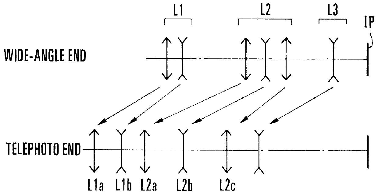
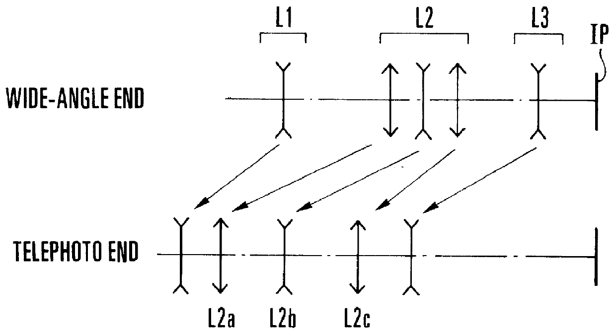
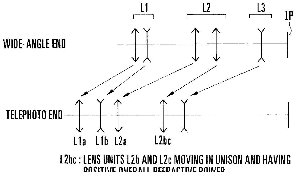
FIG. 66 to FIG. 68 are diagrams to explain the paraxial refractive power arrangements of numerical examples 11 to 17 of zoom lenses of the invention. FIG. 69 to FIG. 75 are longitudinal section views of the zoom lenses of numerical examples 11 to 17 of the invention, respectively. FIG. 76A to FIG. 96D show the aberrations of the numerical examples 11 to 17 of the invention.

In these drawings, L1 is the first lens group of negative refractive power, L2 is the second lens group of positive refractive ...

numerical example

The Values of Aspheric Coefficients:

TABLE 3

It will be appreciated from the foregoing that according to the present embodiment, the entire system is made up from four lens groups and rules of design for these lens groups are set forth to give proper moving conditions and refractive power arrangements, thus achieving a zoom lens having a maximum field angle of about 74.degree. and a zoom ratio of about 3.5 with high optical performance throughout the entire zooming range.


PUM


Abstract

A zoom lens is disclosed, comprising, from front to rear, a first lens group of negative refractive power, a second lens group of positive refractive power and a third lens group of negative power, zooming being performed by varying a separation between each adjacent two of the lens groups, wherein for an object at infinity, an aspheric sphere of such shape that a negative refractive power gets progressively stronger toward the margin is applied to a lens surface of negative refracting power concave toward the object side which satisfies the following condition: Hiw>|Hbiw|Hit>|Hbit|where Hiw (Hiw>0) and Hit (Hit>0) are the heights of incidence for the wide-angle end and the telephoto end of the on-axial ray of light on the i-th surface, respectively, and Hbiw and Hbit are the heights of incidence for the wide-angle end and the telephoto end of the off-axial principal ray of light from the maximum angle of field on the i-th surface, respectively.

Description

1. Field of the InventionThis invention relates to zoom lenses suited to be used in photographic cameras for 35 mm film, video cameras or still video cameras and, more particularly, to wide-angle high range zoom lenses. Still more particularly, it relates to improvements of the compact form of the entire lens system along with high optical performance by setting forth appropriate rules of design for the construction and arrangement of the constituent lenses in each of the lens groups and by applying aspheric surfaces of appropriate shapes to prescribed lens surfaces.2. Description of the Related ArtIt has been known to provide a zoom lens in which the leading lens group is negative in the refractive power as one of the zoom types. This so-called "negative lead" type is relatively feasible for widening the angle of field and has found its use in many wide-angle zoom lenses of not less than 70.degree. in the maximum angle of field.For example, Japanese Patent Publication No. Sho 59-16...

Claims


Application Information

Patent Timeline
Patent Type & Authority Patents(United States)
IPC IPC(8): G02B15/177
CPCG02B15/177G02B15/143503G02B15/144507
Inventor KATO, TAKASHINISHIO, AKIHIRO
Owner CANON KK
Why Eureka
Try Eureka