

Injection molding method for resin-sealed component
- Summary
- Abstract
- Description
- Claims
- Application Information
AI Technical Summary
Benefits of technology
Problems solved by technology
Method used
Image

Examples
embodiments 1 to 4
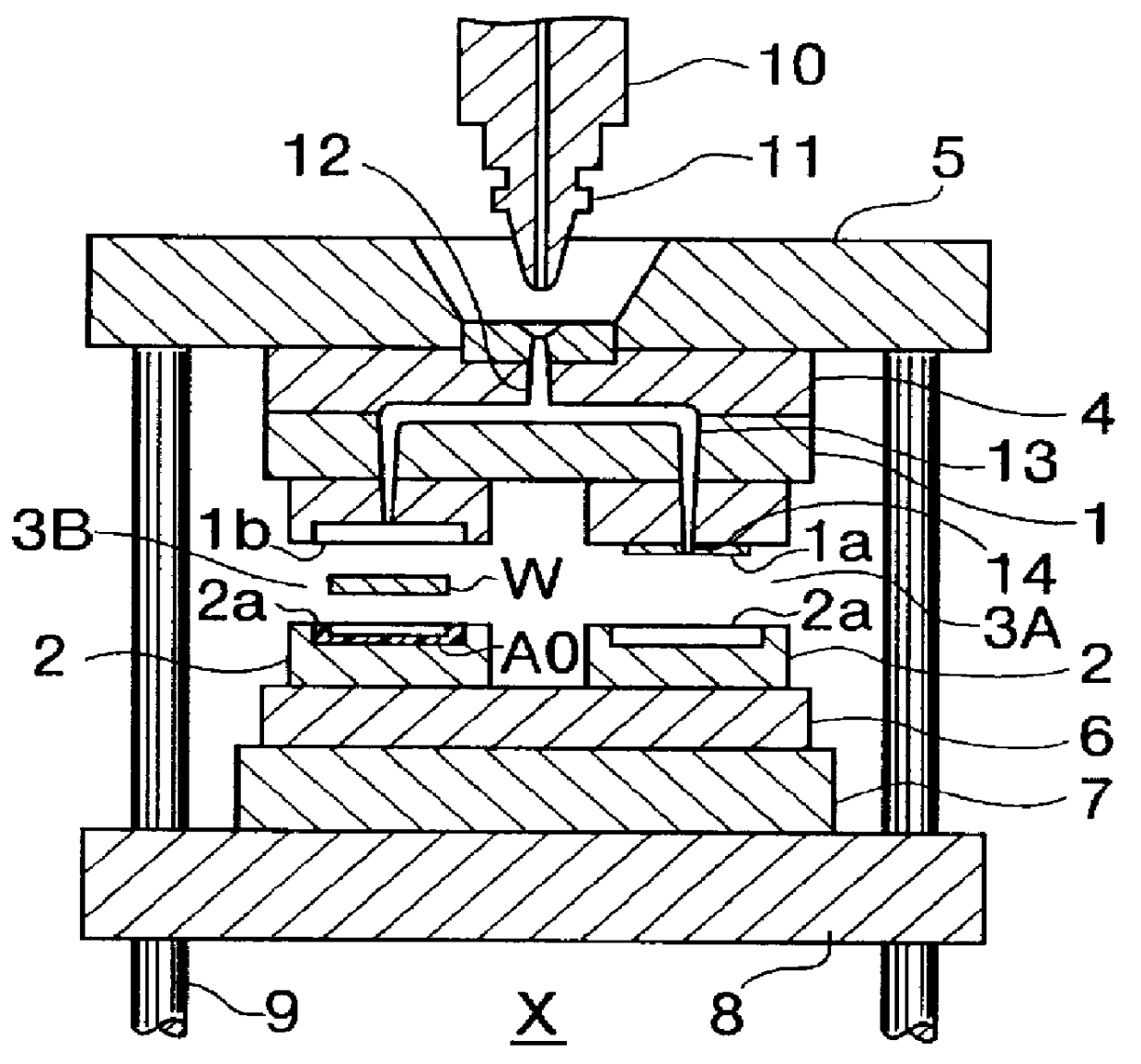
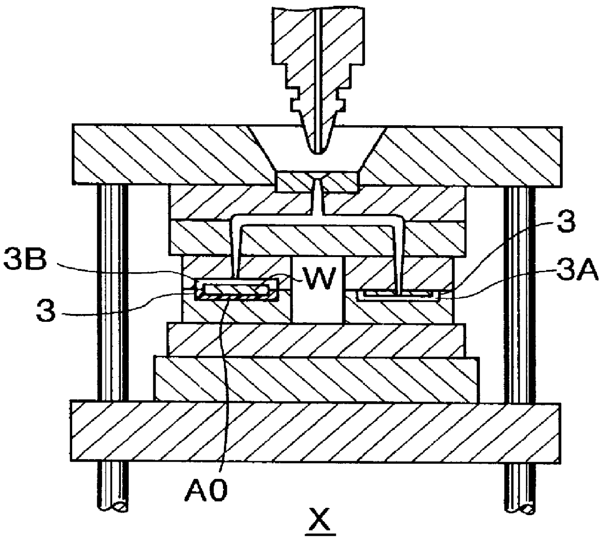
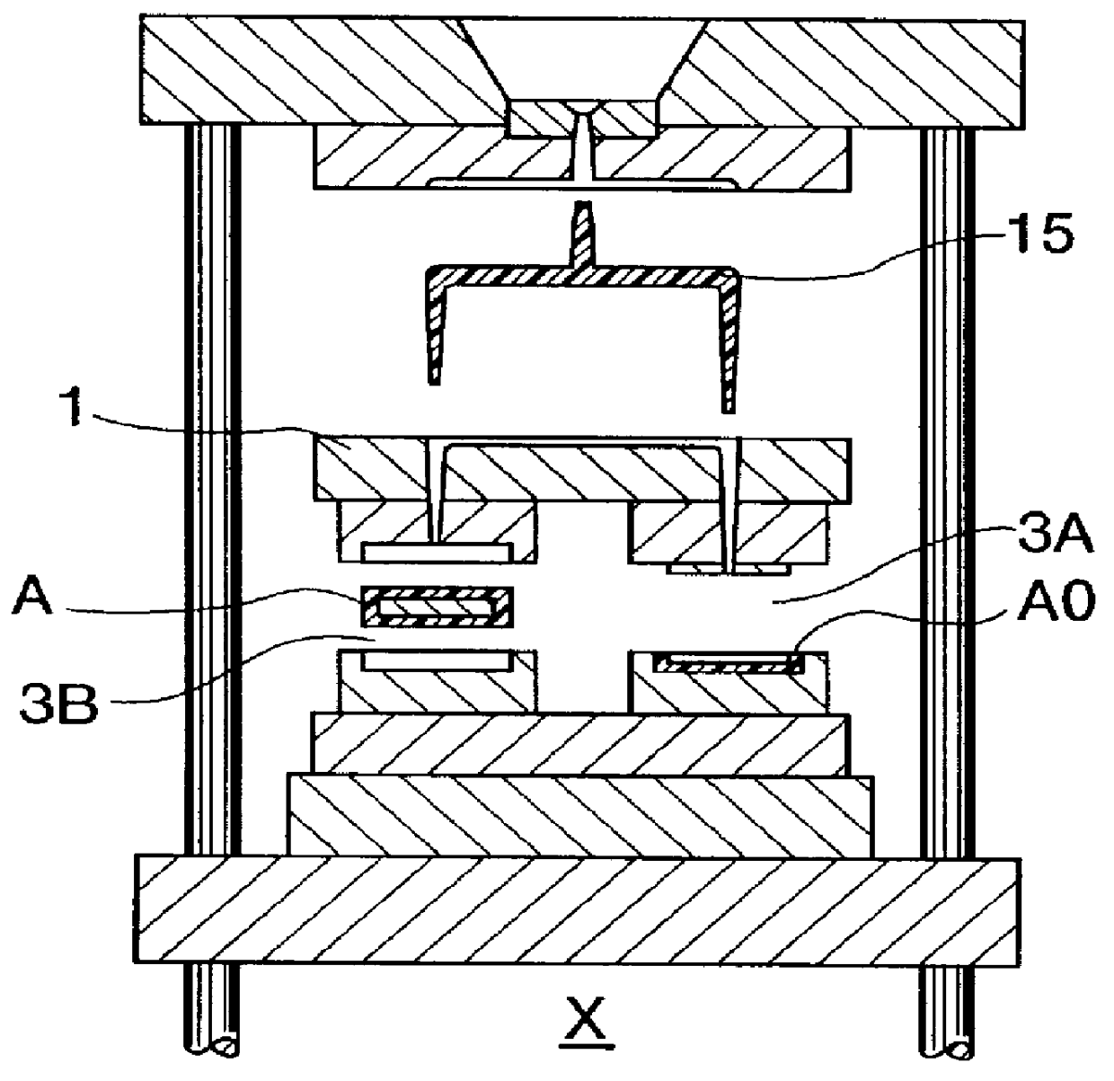
The embodiments 1 to 4 shown in FIGS. 1 through 16 serve to fulfill the injection molding methods described above according to the present invention, and the embodiments 5 and 6 are relevant to the electronically detectable sheet-like indicator of the invention.
Prior to describing these embodiments in detail, the outlines of the embodiments will be given.
##s 1 and 2
The embodiments 1 and 2 are both concerned with a single-head type injection molding method, but different in molding process from each other. That is, the component part to be sealed is inserted after the primary molding process in the embodiment 1, but before the primary molding process in the embodiment 2.
##diments 3 and 4
The embodiments 3 and 4 are both concerned with a twin-head type injection molding method, but different in molding process from each other. That is, the component part to be sealed is inserted after the primary molding process in the embodiment 3, but before the primary molding process in the embodiment 4.
The embodiments 5 and 6 are both concerned with the electronically detectable sheet-like indicator, but different in usage. The indicator of the embodiment 5 is used for tableware, and that of the embodiment 6 is used as a studded paving block to aid visual handicapped people.
PUM
| Property | Measurement | Unit |
|---|---|---|
| Time | aaaaa | aaaaa |
| Shape | aaaaa | aaaaa |
Abstract
Description
Claims
Application Information