Method of assembling a fence

a technology of modular fences and fence posts, applied in fencing, metal working apparatus, manufacturing tools, etc., can solve the problems of laborious and time-consuming fastening practices, and achieve the effect of simple design and easy assembly

Inactive Publication Date: 2000-03-28
KROY BUILDING PROD
View PDF17 Cites 60 Cited by
  • Summary
  • Abstract
  • Description
  • Claims
  • Application Information

AI Technical Summary

Benefits of technology

It is therefore an object of the present invention to provi...

Problems solved by technology

Some systems require the laborious and time consuming practice of fas...

Method used


Image

  • Method of assembling a fence
  • Method of assembling a fence
  • Method of assembling a fence

Examples


Embodiment Construction

For the purposes of promoting an understanding of the principles in accordance with the invention, reference will now be made to the embodiments illustrated in the drawings and specific language will be used to describe the same. It will nevertheless be understood that no limitation of the scope of the invention is thereby intended. Any alterations and further modifications of the illustrated apparatus, and any additional applications of the principles of the invention as illustrated herein, which would normally occur to one skilled in the relevant art and possessed of this disclosure, are to be considered within the scope of the invention claimed.

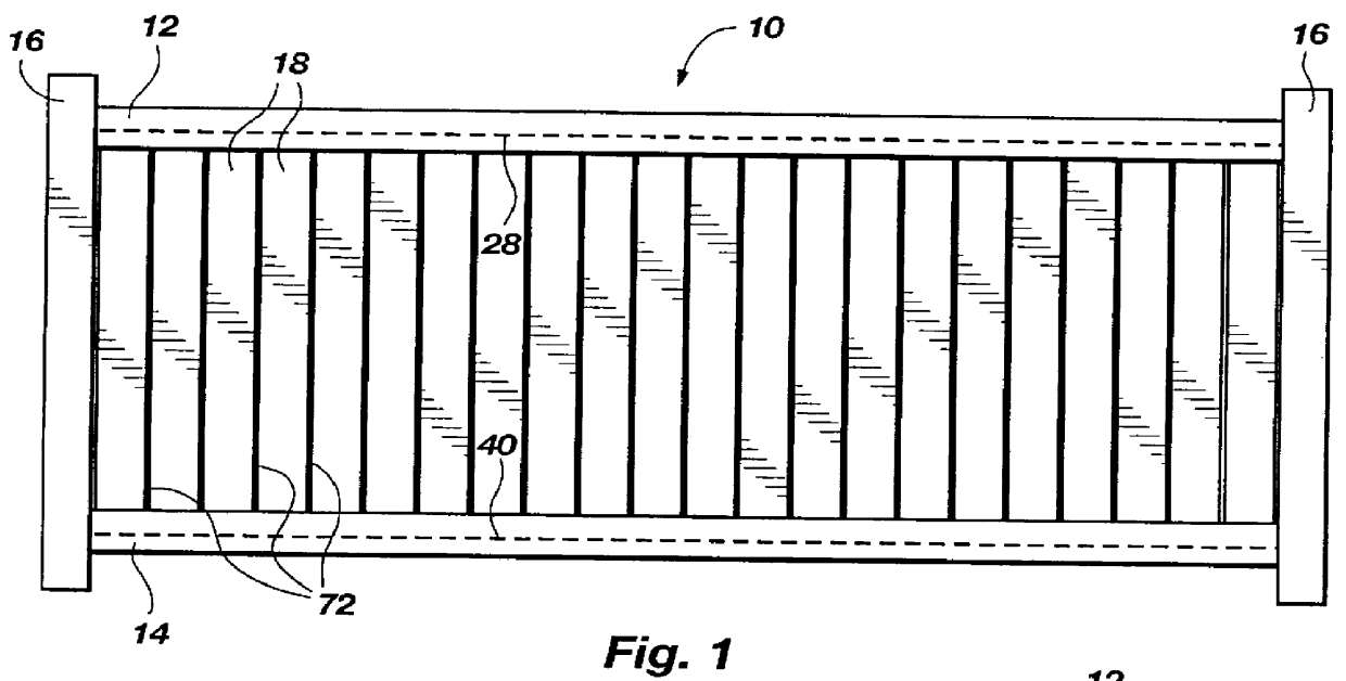
Applicant has discovered that a modular fence system can be designed that is easier to assemble, and requires a lower frequency of intermittent support posts. Applicant's inventive combinations as disclosed herein provide a fence system that requires less time to install, but is structurally sound and aesthetically pleasing.

Referring now t...


PUM

PropertyMeasurementUnit
Widthaaaaaaaaaa

Abstract

A modular fence system. The system includes fence planks designed for insertion into open channels of upper and lower fence rails. The fence rails are supported in a horizontal orientation between intermittent fence posts, with the fence planks extending vertically between the rails. The planks include resilient protrusions at their upper ends. The protrusions of the planks are designed to fit into internal passages formed in the open channels of the upper fence rail, into engagement with ledges defining the passages, to inhibit inadvertent removal of the planks from the upper rail.

Description

1. The Field of the InventionThe present invention relates generally to modular fence systems. More particularly, it concerns a modular fence plank that is lockably insertable into an channel of a fence rail.2. The Background ArtModular fence systems are becoming increasingly popular with home owners and businesses alike. Vinyl polymeric fence components have been designed for use in assembling an attractive fence.The prior art modular fence systems are characterized by a number of disadvantages. Some systems require the laborious and time consuming practice of fastening the fence components with nuts and bolts or other fastening devices. Some of the more decorative-oriented fence systems utilize a lower fence rail to support substantially the entire weight of the planks of the fence, a design that requires a higher frequency of intermittent support posts to inhibit sagging in the lower fence rail.OBJECTS AND SUMMARY OF THE INVENTIONIt is therefore an object of the present invention...

Claims


Application Information

Patent Timeline
IPC IPC(8): E04H17/14E04H17/16
CPCE04H17/1417E04H17/16Y10T29/49876E04H2017/1469E04H17/1469
Inventor FORBIS, JOHN T.
Owner KROY BUILDING PROD
Why Eureka
Try Eureka