Connector for flat conductive path

a technology of connecting wires and conductive paths, applied in the direction of fixed connections, coupling contact members, coupling device connections, etc., can solve the problem of adversely affecting the reliability of the connection

Inactive Publication Date: 2000-03-28
SUMITOMO WIRING SYST LTD
View PDF6 Cites 9 Cited by
  • Summary
  • Abstract
  • Description
  • Claims
  • Application Information

AI Technical Summary

Problems solved by technology

However, there is the problem that if the locking of the cover c is secure, as mentioned above, it takes time to open the cover c, but if the operation of opening the cover c is given priority and the locking force of the cover c accordingly made weaker, the reliability of the connection is adversely affected.

Method used


Image

  • Connector for flat conductive path
  • Connector for flat conductive path
  • Connector for flat conductive path

Examples


Embodiment Construction

An embodiment of the present invention is described below with the aid of FIGS. 1 to 9.

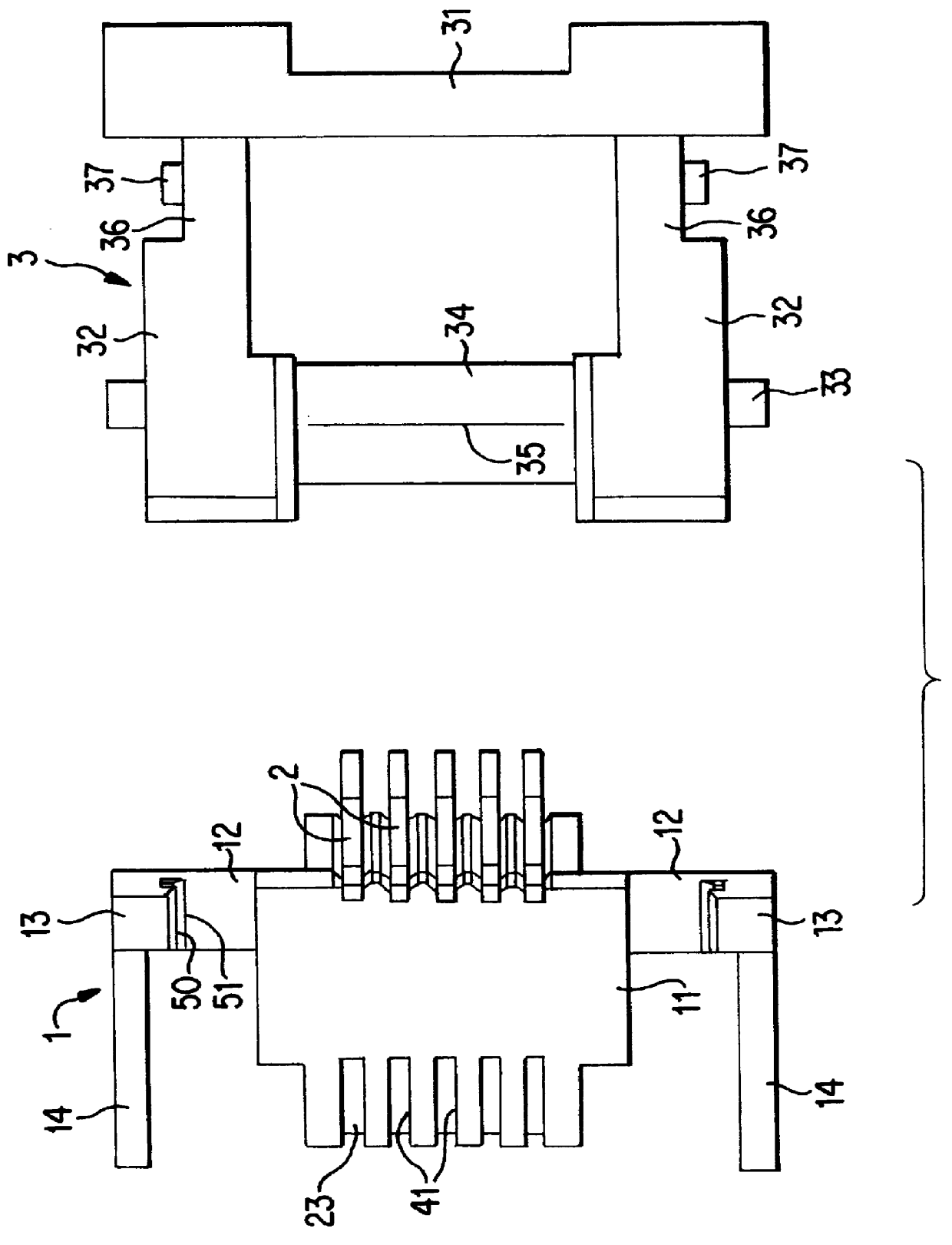
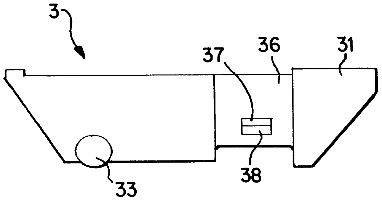
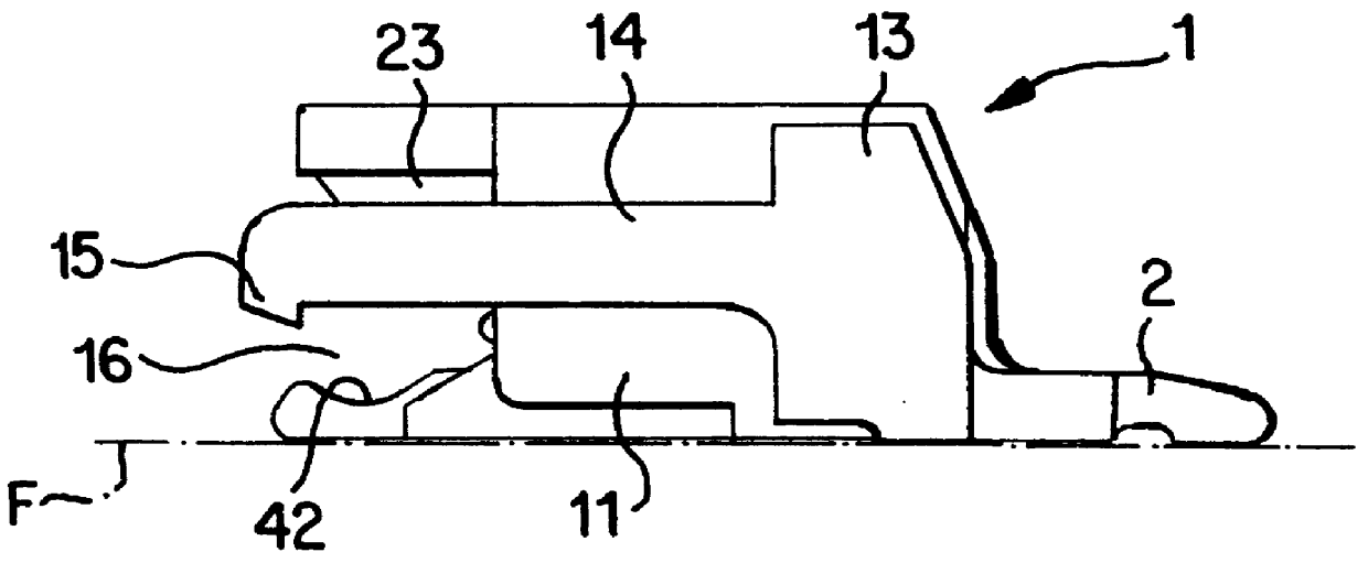
As shown in FIG. 1, a connector comprises a connector housing 1, a plurality of terminals 2 attached to the housing 1, and a pressing member 3 attached in a pivotable manner to the housing 1. A sheet-like electrically conductive path suitable for use in this embodiment is a ribbon cable 4 comprising a flexible printed circuit or FPC (see FIG. 10), and has a configuration whereby the upper face of a bendable sheet-like base member has a plurality (five in the present embodiment) of evenly spaced conductive paths (not shown) formed thereon by a print distributing means, the anterior end of each conductive path making contact with contact members 24 of the terminals 2.

The housing 1 is formed in a unified manner from synthetic resin and, as shown in FIGS. 1 and 2, has a block-like main body 11. As shown in FIG. 3, protruding members 12 protrude to the left and right sides from the lower portion of the...


PUM


Abstract

An electrical connector for a ribbon cable comprises a housing (1) with a pivotable pressing member (3) movable from an open to a closed condition to clamp a cable (4). The pressing member has temporary stopping latch (37,50) to allow a substantially closed connector for transport for transport and attachment purposes, and a final stoping latch (37,51) for firm engagement with the cable (4).

Description

The present invention relates to an electrical connector to which a sheet-like electrically conductive path is attachable.BACKGROUND TO THE INVENTIONA well-known example of a connector for a strip or sheet-like electrically conductive path is disclosed in the Laid-Open Publication Tokkaihei 8-279378. As shown in FIGS. 10 and 11 of this specification, a ribbon cable connector is provided with a plurality of terminals a housed in a parallel manner within a connector housing b, and a cover c which can be opened to a releasing position or closed to a pressing position with respect to the connector housing b. When the cover c is in the releasing position, a ribbon cable d can be inserted between the cover c and the terminal a. This ribbon cable d is clamped between the cover c and the terminal a when the cover c is closed to the pressing position, thus electrically connecting the ribbon cable d with terminal a. Locking members e and f are provided on the cover c and the housing b in orde...

Claims


Application Information

Patent Timeline
Patent Type & Authority Patents(United States)
IPC IPC(8): H01R13/02H01R13/193H01R12/57H01R12/79H01R12/88
CPCH01R12/79H01R12/88H01R13/193H01R12/57
Inventor NORO, YUTAKA
Owner SUMITOMO WIRING SYST LTD
Why Eureka
Try Eureka