Method and apparatus for cooling an electronic device

a technology for electronic devices and cooling devices, applied in lighting and heating apparatus, indirect heat exchangers, semiconductor/solid-state device details, etc., can solve the problems of inapplicability to standard semiconductor packaging techniques, the ultimate performance of air-cooled heat sinks is limited by available space, and the length of fins is increased

Inactive Publication Date: 2000-04-18
IBM CORP
View PDF14 Cites 105 Cited by
  • Summary
  • Abstract
  • Description
  • Claims
  • Application Information

AI Technical Summary

Benefits of technology

It is a still further object of the present invention that the heat transfer efficiency be nearly independent of fin thickness and thermal conductivity as long as sufficient fin velocity relative to the electronic component is maintained. The fin can therefore be made of lightweight plastic materials.

Problems solved by technology

If the fins get too long, the tips of the fins approach ambient temperature and an increase in fin length no longer improves the thermal performance.
The ultimate performance of an air cooled heat sink will be limited by available space, air flow and weight.
Extremely good thermal performance is obtained but the system is massive and not applicable to standard semiconductor packaging techniques.
This device is large and the fan tends to generate loud audible noise.
U.S. Pat. No. 5,504,924 to Ohashi et. al. utilizes a heat pipe as one of its components, but to make the heat pipe effective one end is attached to a large cooling unit which is quite cumbersome.
Relatively high speeds are required and the unit is far too large for dense, lightweight, low power applications needed for semiconductor chips.
Thus high performance cooling methods can be quite large, heavy, or consume large amounts of power or generate audible noise which are undesirable in small equipment or portable computers.

Method used


Image

  • Method and apparatus for cooling an electronic device
  • Method and apparatus for cooling an electronic device
  • Method and apparatus for cooling an electronic device

Examples


Embodiment Construction

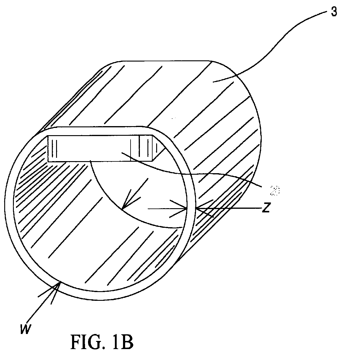
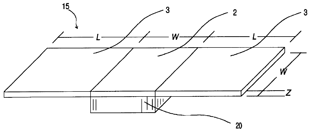
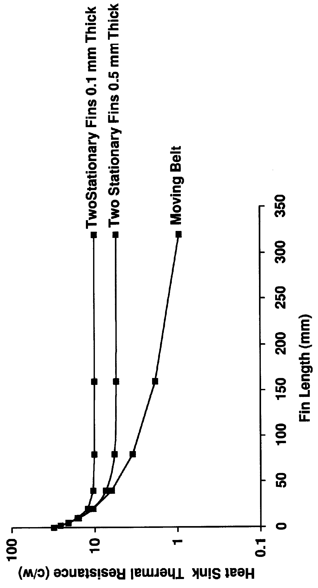
The advantage of the current invention can be realized by comparing its thermal performance to a conventional finned air colled electronic module heatsink. It will be immediately recognized by one skilled in the art that the invention is equally applicable to use with other heat transfer fluids such as liquids and gasses, other thermal control problems in other industries. The predominate heat transfer mechanism does not need to be limited to convection and could include contact and radiation heat transfer from the moving fin. Attention is directed to FIG. 1A heat sink 15 which is in contact with an electronic module 20, the heat sink has a square isothermal base 2 of dimension "w" which is typically about the same size as the electronic devices, such as semiconductor modules. Space above the module is limited so fins 3 are added to opposite edges of the base. The thermal performance of this heat sink can be estimated by making some simplifying assumptions. There are two fins 3 of w...


PUM


Abstract

A heat dissipation apparatus for cooling one or more electronic devices. The apparatus utilizes a moving heat sink a portion of which is in contact with the device to be cooled. The moving heat sink may be in the form of a rotating disk, moving belt or strip. The heat sink may be made from various materials such as metals or plastics.

Description

FIELD OF THE INVENTIONThe present invention relates to the field of cooling of electronic components; more specifically, it relates to an apparatus and a method for enhancing the removal rate of heat generated by electronic components.BACKGROUND OF THE INVENTIONHigh performance microprocessor devices and the like concentrate heat in a very small space which require improved thermal cooling to maintain acceptable operating conditions. There are numerous different solutions to overcome this problem which are used in different applications such as thermally conductive pistons, micro bellows, water cooled cold plates, heat sinks, heat pipes and fans. A conventional technique used to improve thermal performance is to add finned heat sinks to increase the available surface area. Making the fins longer provides increasing thermal performance up to a point. If the fins get too long, the tips of the fins approach ambient temperature and an increase in fin length no longer improves the therma...

Claims


Application Information

Patent Timeline
Patent Type & Authority Patents(United States)
IPC IPC(8): F28D19/00F28D19/04H01L23/34H01L23/36
CPCF28D19/04H01L23/36F28F5/00H01L2924/0002F28D2021/0028F28F2215/14H01L2924/00
Inventor EVANS, RICHARD J.GARDELL, DAVID L.PALAGONIA, ANTHONY M.
Owner IBM CORP
Why Eureka
Try Eureka