Intravenous site protection device

a protection device and intravenous technology, applied in the field of intravenous site protection devices, can solve the problems of extreme consequences for patients, partial or complete catheter removal, etc., and achieve the effect of convenient monitoring

Inactive Publication Date: 2000-04-25
PADILLA JR JAMES D
View PDF5 Cites 10 Cited by
  • Summary
  • Abstract
  • Description
  • Claims
  • Application Information

AI Technical Summary

Benefits of technology

The technical effect of this patent is that it provides a protective cover for IV sites made from a strong, clear material that allows healthcare professionals to easily monitor patients during transport. This helps ensure safe delivery of care while moving patients around within a facility or between facilities.

Problems solved by technology

The technical problem addressed in this patent is how to create an effective and efficient intravenous site protection device that prevents damage to the IV catheter while keeping the patient mobile. This device should be comfortable, easy to apply and remove, and made from a clear plastic material for easy monitoring by healthcare professionals.

Method used


Image

  • Intravenous site protection device
  • Intravenous site protection device
  • Intravenous site protection device

Examples


Embodiment Construction

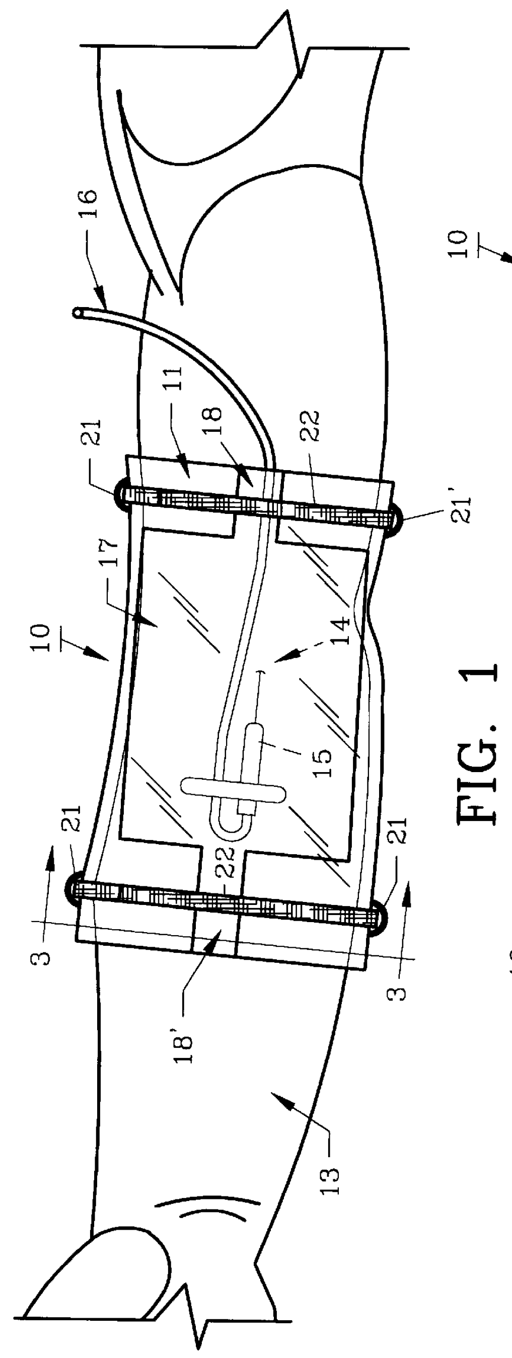
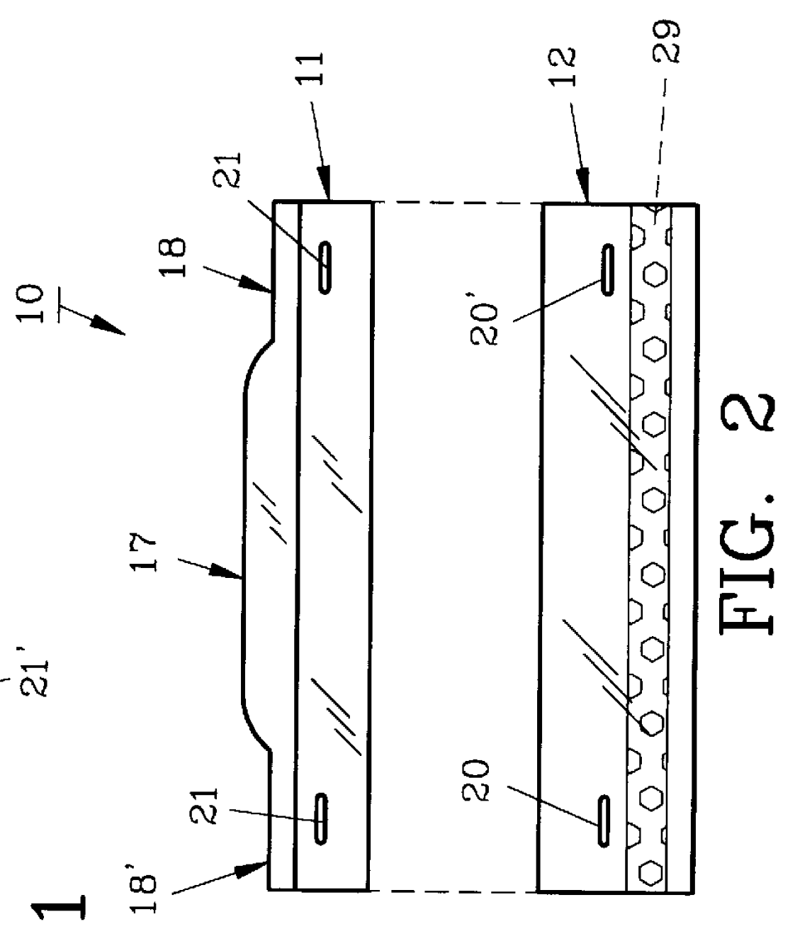
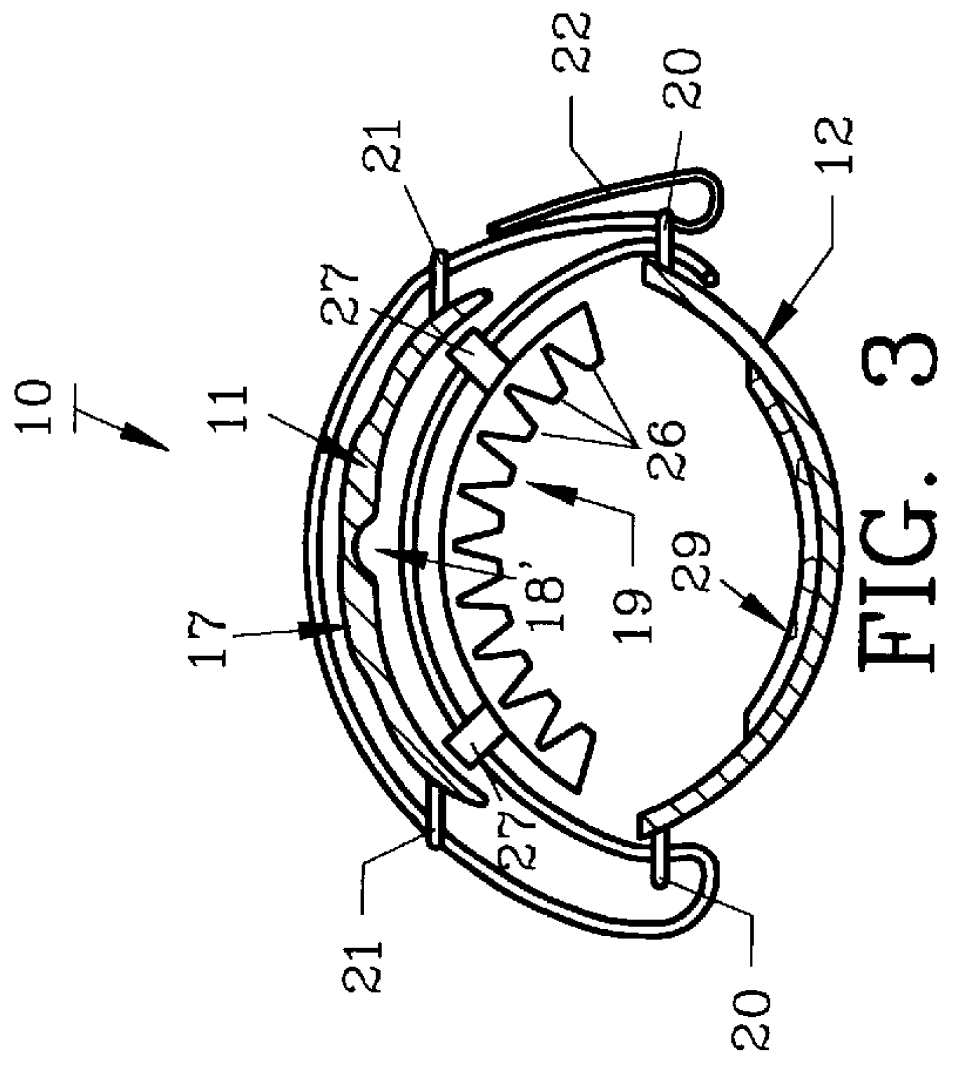
For a better understanding of the invention and its operation, turning now to the drawings, the preferred form of intravenous site protection device 10 is shown in FIG. 1, 2 and 3 which includes a transparent, elongated, rigid top member 11 having an arcuate transverse cross-section as shown in FIG. 3 and an elongated, rigid arcuate bottom member 12. Top member 11 and bottom member 12 may be formed of suitable polymeric materials such as polyacrylic or polycarbonate plastics which are commercially available and can be molded to the exact size and shape required. For example, various size intravenous site protection devices 10 can be manufactured for infants, small children or small, medium and large adult sizes.

Top member 11 and bottom member 12 are positioned on the wearer's arm 13, as shown in FIG. 1, to protect intravenous site 14 having catheter 15 in place for delivering fluid into patient's arm 13 through supply tube 16. As understood, various medication, or other fluids can b...


PUM


Abstract

An intravenous site protection device is formed with a rigid, elongated top member and a rigid, elongated bottom member which are oppositely secured on a patient's extremities. The top member is configured to accommodate a catheter and supply tubing to prevent accidental dislodgement during transportation or movement of the patient. Securing straps maintain the top and bottom members against the extremity of the wearer and a resilient sponge is positioned beneath the top member, against the wearer's skin, to assure proper circulation to the intravenous site. The rigid plastic ensures protection of the intravenous site should the site be struck or contacted with clothing or other articles during intravenous fluid transfer. The preferred form of the invention is made from a transparent plastic to allow ease in monitoring by medical personnel.

Description


Claims


Application Information

Patent Timeline
Owner PADILLA JR JAMES D
Why Eureka
Try Eureka