Cutting, jointing and tearing volumetric objects

a volumetric object and jointing technology, applied in the field of volume graphics, can solve the problems of difficult construction of cutting plane surfaces, difficult modeling of cutting through surface-based objects, and significant demands on the surgical simulator

Inactive Publication Date: 2000-04-25
MITSUBISHI ELECTRIC RES LAB INC
View PDF5 Cites 31 Cited by
  • Summary
  • Abstract
  • Description
  • Claims
  • Application Information

AI Technical Summary

Benefits of technology

In the presently disclosed modeling technique, a volumetric model is augmented with connecting links between neighboring elements. Interactive object manipulation techniques use this representation, allowing links to be created and destroyed according to the paths traversed by a simulated tool, such as a cutting tool or a joining tool. These techniques allow the physically-plausible simulation of object cutting, tearing and joining.
With a volumetric object representation, the interior structure that is revealed

Problems solved by technology

These requirements impose significant demands on the surgical simulator and more particularly, they require physically realistic modeling techniques which simulate soft tissue deformation, tissue cutting, tearing or joining.
Modeling of cutting through surface-based objects is difficult because new contiguous surfaces must be constructed along the cutting path.
If the cut can be made through arbitrary positions in the model, construction of cutting plane surfaces can be quite difficult.
While these volumetric sculpting techniques have potential applications in volume editing and geometric design, it is important to note that the resultant array of intensity values lacks the physical sense of being an object.
Once pieces in the array are "carved" away from the rest of the volume, they cannot be manipulated as individual objects.
Material is created and disso

Method used


Image

  • Cutting, jointing and tearing volumetric objects
  • Cutting, jointing and tearing volumetric objects
  • Cutting, jointing and tearing volumetric objects

Examples


Embodiment Construction

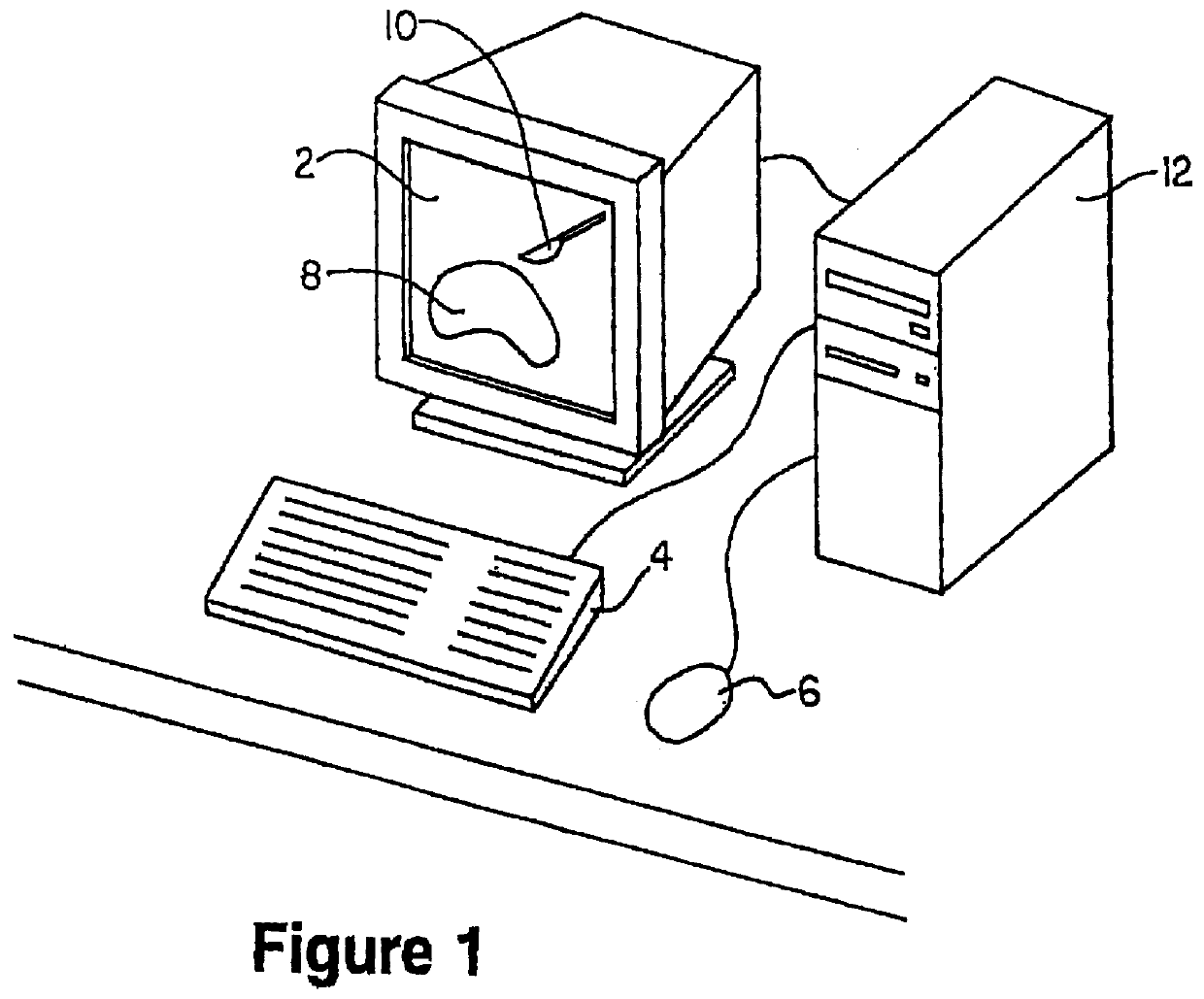
Referring to FIG. 1, a system for cutting, tearing, and joining graphical objects includes a computer monitor 2, for visualizing the simulation, a keyboard 4, and / or other input device 6 for controlling an object 8 displayed on the monitor 2, and an acting tool 10 such as the cutting tool 10 and a computer, 12.

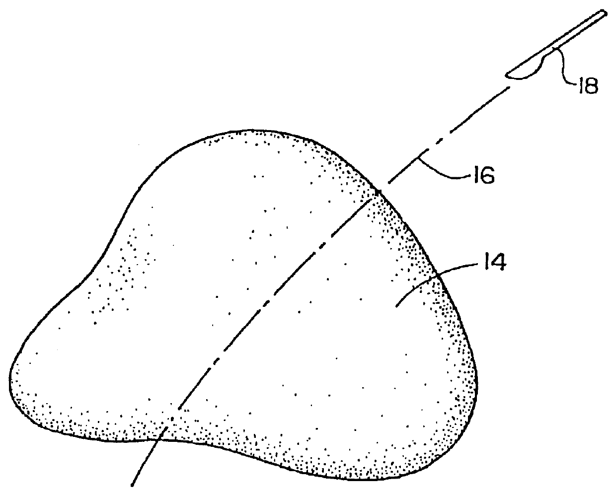
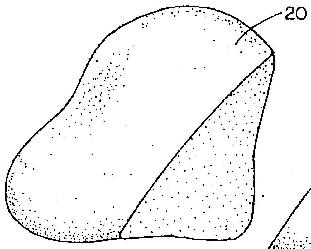
FIG. 2a illustrates the cutting a graphical object 14, along a tracing path 16 via use of a graphical tool 18, and FIG. 2b illustrates the object of FIG. 2a after slicing with the graphical tool 18. For surface-based objects, the result is first and second hollow pieces 20 and 22 respectively for which a face created as the the consequence of the cutting of the object must be generated.

Referring to FIG. 3a, a surface-based object 24 is represented by abutting surface patches, e.g. patches 26, 28, 30. When the object is sliced along the path 32 by the graphical cutting tool 34, a new viewable surface 36 must be created. The new surface 36 is defined by new abutting surface patc...


PUM


Abstract

A linked volumetric representation for graphical objects is presented together with techniques for physically-plausible modeling of object cutting, joining and tearing. In one embodiment, each element is may be explicitly linked to its six nearest neighbors by storing pointers to those neighbors in the element's data structure. The link between two elements can be cut when a graphical representation of cutting tool passes between the elements by setting the appropriate neighbor pointers in the two elements to point to NULL instead of to each other. If material limits in the link between two elements are exceeded during simulation of object deformation, the link can be torn apart by setting the appropriate neighbor pointers in the two elements to NULL. When a joining tool is applied to two volumetric objects in close proximity, edge elements in the two objects that have complimentary neighbors set to NULL can be joined by setting these missing neighbors to point to each other.

Description

BACKGROUND OF THE INVENTIONThe present invention pertains to volume graphics and more specifically, to a technique for graphically modeling the cutting of volumetric objects along an arbitrary cutting path, the joining together of volumetric objects of arbitrary shape at an arbitrary surface, and the tearing of deformable volumetric object models when they are pulled apart.Computer based simulation has many applications. One such application involves surgical simulation. Computer based surgical simulation has application in surgical training, education, surgical planning and with intra-operative assistance. In medical education and training, surgical simulation can reduce costs associated with cadaver specimens, provide experience with a greater variety of pathologies and complications that would normally be encountered in practice, and provide the ability to repeat or replay training procedures. In surgical planning, simulators enable rehearsal of difficult procedures or planning o...

Claims


Application Information

Patent Timeline
IPC IPC(8): G06T17/00G06T19/20G09B9/00
CPCG06T17/00
Inventor GIBSON, SARAH F.
Owner MITSUBISHI ELECTRIC RES LAB INC
Why Eureka
Try Eureka