Imprintable tape with tear lines defining asymmetrical identification bracelets

a technology of asymmetrical identification and imprinting tape, applied in the field of identification bracelets, can solve the problems of time-consuming and labor-intensive procedures, and achieve the effects of reducing labor intensity, improving appearance, and eliminating or greatly reducing disadvantages

Inactive Publication Date: 2000-05-09
PRECISION DYNAMICS CORPORATION
View PDF15 Cites 54 Cited by
  • Summary
  • Abstract
  • Description
  • Claims
  • Application Information

AI Technical Summary

Benefits of technology

One aspect of this invention therefore lies in the recognition that such disadvantages may be eliminated or greatly reduced by providing separable bracelets in tape form with each bracelet being asymmetrical in shape. More specifically, each bracelet has an imprintable portion extending the full width of the tape and relatively narrow strap and tab portions offset at opposite ends of the imprintable portion. The strap and tab portions are aligned along one side edge of the tape, leaving relatively wide and easily graspable and removable waste sections extending only along the opposite side edge of the tape.
Such a construction yields significant advantages. When the waste sections are removed, each bracelet has relatively narrow strap and tab portions that compared to a machine-imprintable band of uniform width, improve its appearance and make it more comfortable to wear. Removal of the waste sections is facilitated because they extend along only one side of the tape and are relatively wide, approximating the width of the strap portions themselves, and are therefore easily grasped for removal. Further, because of their substantial width, each waste section may be provided with a sensor opening of the type used by conventional tape printers for controlling the automatic advancement and location of tape through the machines. Such openings in no way weaken the final bracelets because the sensor openings are not located in their strap portions but instead are disposed along the waste sections that are discarded after the tapes have been printed.

Problems solved by technology

While such width may be necessary in the central imprintable area to accommodate medical information, it is believed to be clearly undesirable along the strap portion of the bracelet because it reduces conformability, is visually objectionable, and is often likely to cause patient discomfort.
While bracelets are known that have relatively wide information-receiving portions and narrow strap portions (see, for example, U.S. Pat. Nos. 4,914,843, 5,581,924, 3,467,246), such bracelets have generally not been provided in roll form for use with machine printers because reliability and effectiveness of printer operations require tape of substantially uniform width.
A possible alternative might be to provide a tape of uniform width with removable portions that could be detached from each side and discarded after the imprinting step; however, such procedures would tend to be time consuming and would largely offset the advantages conferred by automated processing.

Method used


Image

  • Imprintable tape with tear lines defining asymmetrical identification bracelets

Examples


Embodiment Construction

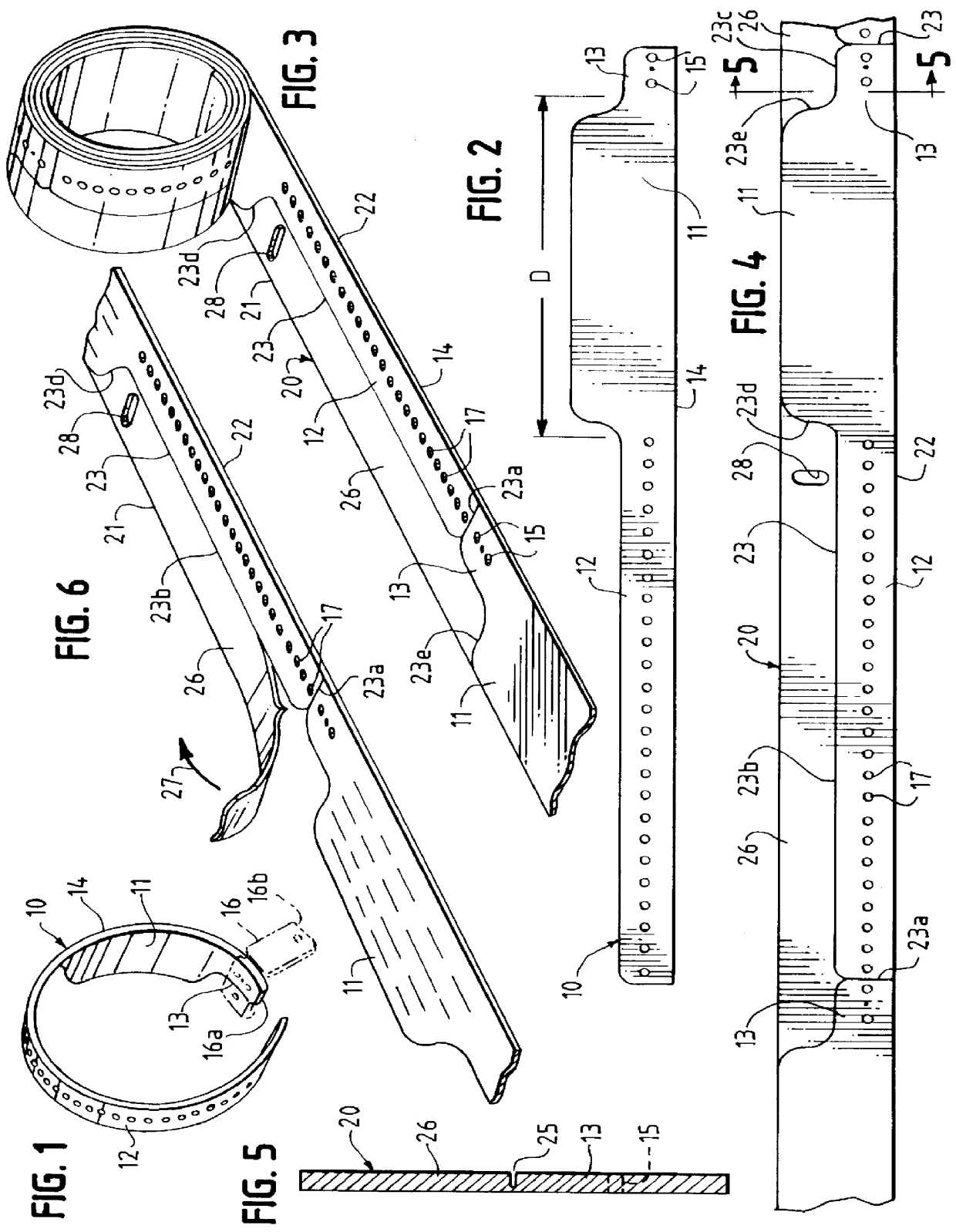
FIGS. 1 and 2 illustrate an identification bracelet 10 of asymmetric outline embodying the invention. The bracelet is formed from a strip of thin, tough, flexible and stretch-resistant material providing an outer surface capable of receiving (or generating) and retaining indicia. A variety of materials having such characteristics are well known in the art. One such material believed to be particularly effective is a tri-laminate of synthetic paper, polyester and textured polyethylene, but other materials having similar properties may be used. Also, as well known in the art, such materials may be surface treated to make them thermally sensitive, allowing indicia to be created on or within the bracelet by heat. In that connection, it is to be understood that the terms "imprint" and "imprintable" are used herein to refer to a surface that may be acted upon by conventional means to provide visible characters from which useful information may be derived, either visually or by means of sc...


PUM


Abstract

A machine-imprintable tape, most advantageously provided in roll or coil form, is disclosed. The tape has lines of weakness constituting tear lines that define a longitudinal series of asymmetric identification bracelets, each bracelet having a generally rectangular imprintable portion, an elongated strap portion at one end of the imprintable portion, and a connecting tab portion at the opposite end of the imprintable portion. The imprintable portion has a width equal to that of the tape; the strap and tab portions are substantially narrower and are arranged along one side edge of the tape to leave removable waste sections extending along only the opposite side edge of the tape. To control advancement of the tape through a printer, each waste section may be provided with a locator opening detectable by an optical sensor of the printer.

Description

BACKGROUND AND SUMMARYIt is known to provide patient identification bracelets joined end-to-end in roll form so that such bracelets may be fed through a printer, such as a direct thermal printer or a thermal transfer printer. Following imprinting, each bracelet is separated from the roll and fitted about a patient's wrist or ankle. For example, U.S. Pat. No. 5,799,426 discloses a roll of tape of uniform width which may be fed through a computerized printer, the tape being in the form of separable sections joined end-to-end. After each bracelet is printed and separated from the remainder of the tape, its opposite ends may be adhered together to form a closed loop.Each bracelet of U.S. Pat. No. 5,799,426 is of uniform width. While such width may be necessary in the central imprintable area to accommodate medical information, it is believed to be clearly undesirable along the strap portion of the bracelet because it reduces conformability, is visually objectionable, and is often likely...

Claims


Application Information

Patent Timeline
Patent Type & Authority Patents(United States)
IPC IPC(8): G09F3/00
CPCG09F3/005
Inventor DUNCAN, JULIE A.
Owner PRECISION DYNAMICS CORPORATION
Why Eureka
Try Eureka