Seismic and fire-resistant head-of-wall structure

a head-of-wall structure, seismic and fire-resistant technology, applied in fireproofing, walls, parkings, etc., can solve the problems of destroying, or at least destroying the integrity of the structure, introducing both horizontal and vertical undulations, and spreading fire from room to room within the building

Inactive Publication Date: 2000-05-09
HERREN THOMAS R
View PDF10 Cites 186 Cited by
  • Summary
  • Abstract
  • Description
  • Claims
  • Application Information

AI Technical Summary

Problems solved by technology

One problem which occurs in any building during an earthquake is that the seismic ground motion from an earthquake introduces both horizontal and vertical undulations in the building.
However, vertical undulations that vary the distance between the floor and ceiling in a room during an earthquake are likely to destroy, or at least damage the integrity, of rigid structural joints between vertical metal studs and horizontal sill and overhead beam members between which the studs extend in a building.
Another problem which may occur is the spread of fire from room to room within a building.
Fire paths are particularly likely to develop if the joints between the metal studs in the walls and the ceiling above have been damaged by prior seismic activity.
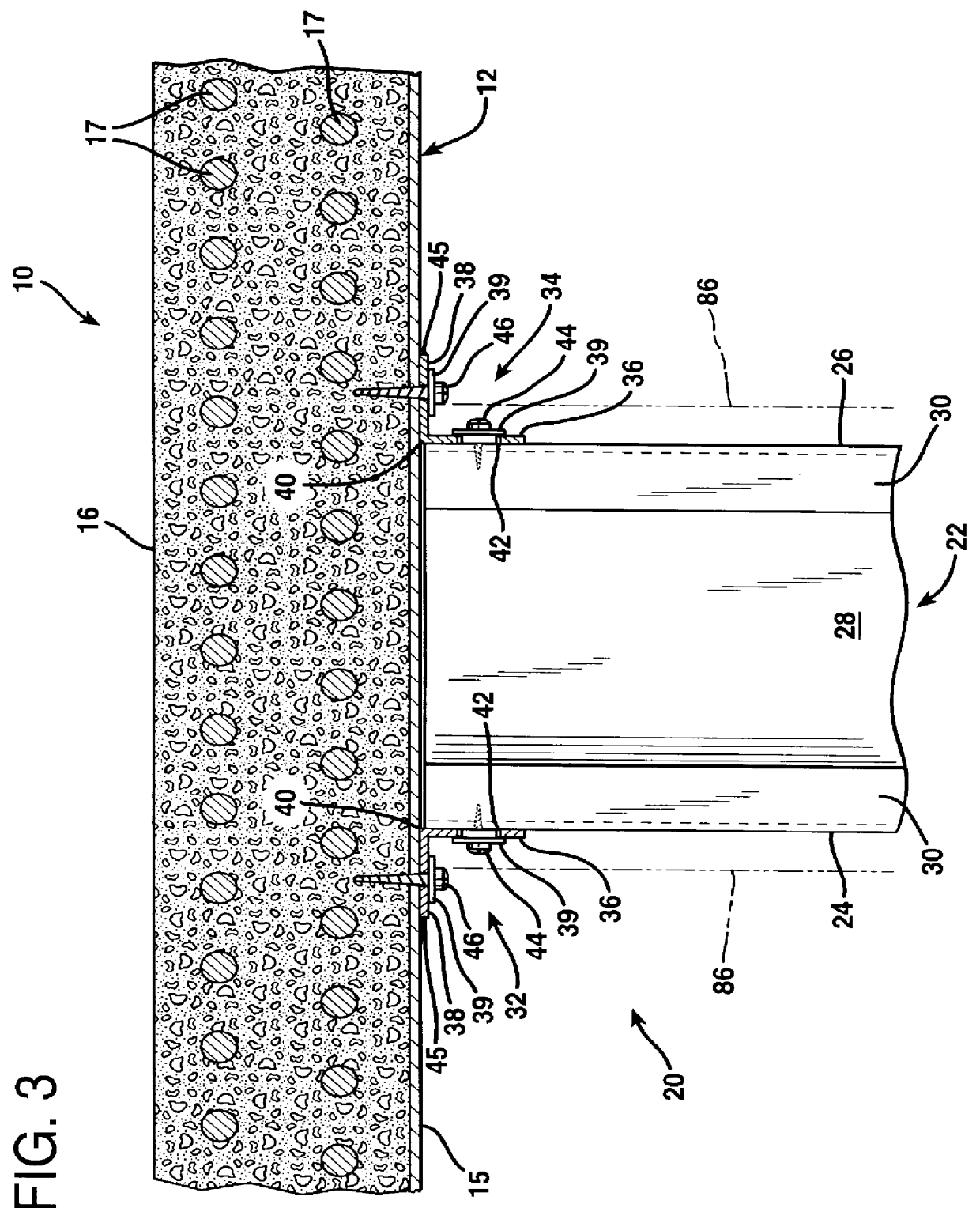
The fasteners, typically sheet metal screws, are tight enough to provide lateral stability at the joints between the studs and the overhead beam, but are not so tight as to prevent relative vertical motion therebetween.
A problem which continues to exist in building construction is the difficulty in making a nonload-bearing wall adequately fire resistant.
When the insulation dries and congeals it clogs the flute openings at the top of the wall.
However, when a fire is burning within a building, it generates a considerable amount of smoke which is heated and expands.
The smoke causes a great pressure within a room where a fire is burning.
It is known that the pressure of smoke from a fire burning within a room literally blasts the fire insulation out of the flute openings atop the wall.
However, this system for holding the insulation in position is extremely time consuming, laborious, and expensive.
Hand cutting of the upper region of the wall to follow the convolutions of the corrugated, fluted decking is extremely labor intensive.
The labor cost in creating a scalloped upper edge at the top of the wallboard adds significantly to the cost of construction of the wall.
Moreover, even if a template is used the hand cuts result in significant gaps remaining which must then be caulked.
The process of caulking is also an extremely laborious, labor intensive process, particularly when it is necessary to follow the convolutions of the underside of the fluted decking.
Moreover, conventional caulking is not seismic resistant.
That is, even if the caulking originally provides an effective barrier to air currents, if the building structure subsequently is subjected to seismic activity, the caulking crumbles and gaps that allow the passage of air currents are opened.
When this occurs the wall no longer offers its original resistance to the spread of fire.
As a result, it has not heretofore been possible to provide both seismic resistance and fire resistance in interior building walls that will meet the stringent building codes applicable to structures such as schools and hospitals.
While the system of U.S. Pat. No. 5,127,203 does allow limited vertical 
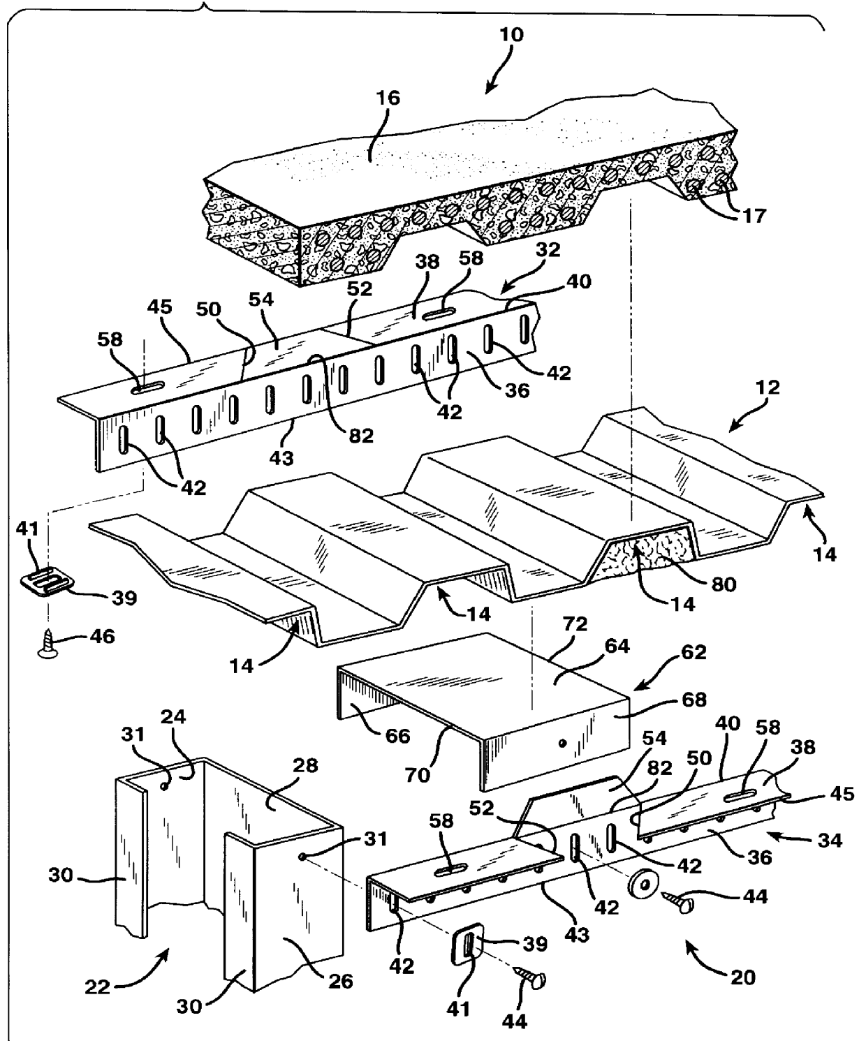
cycling at the head-of-wall structure, it does not provide any means for retaining the insulation within the flutes of decking above the downwardly facing overhead channel-shaped beams.
Thus, it is evident that conventional design features that tend to enhance seismic resistance tend to reduce fire resistance.
That is, if there is considerable play in the joints between upright metal studs and overhead metal beams to which the studs are attached, openings are created which reduce resistance to the passage of fire.
On the other hand, if joints are closed and locked immovably together, they are likely to fail when subjected to seismic activity.
Thus it has heretofore not been possible to provide an interior building wall construction system which meets both the maximum standards for fire resistance and the maximum standards for resistance to seismic movement as well.
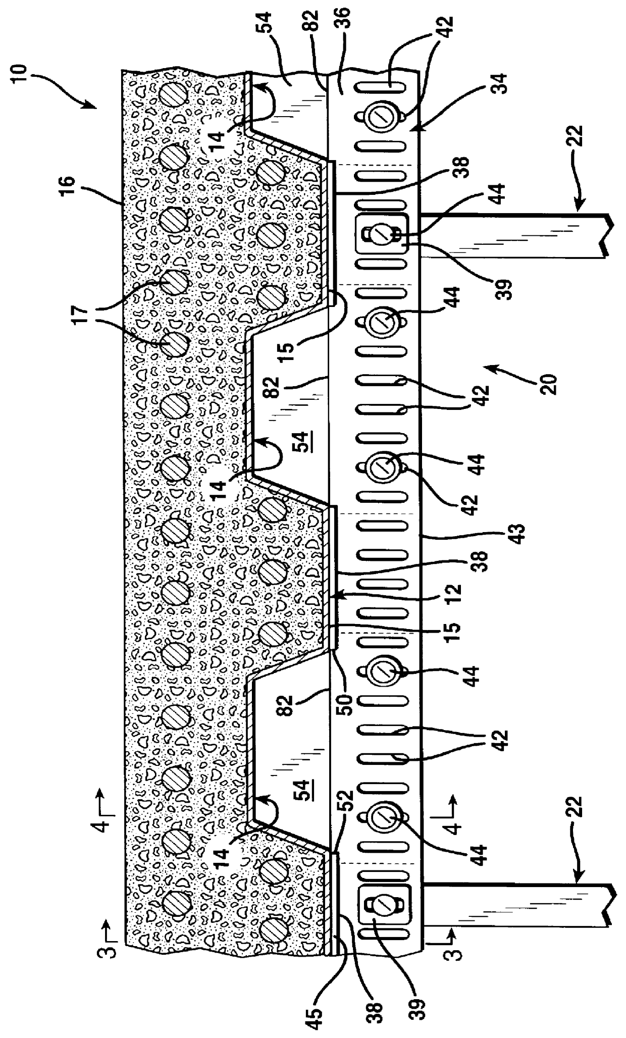
As a consequence, if a fire occurs within a room on one side of the wall, the resultant pressure cannot force the batts of insulation out of their fire blocking positions atop the wall within the ceiling flutes.
This movement is limited by the lengths of the ceiling fastener openings.

Method used


Image

  • Seismic and fire-resistant head-of-wall structure
  • Seismic and fire-resistant head-of-wall structure
  • Seismic and fire-resistant head-of-wall structure

Examples


Embodiment Construction

FIG. 1 illustrates a portion of a building having a floor. A ceiling 10 is formed about nine feet above the floor. The ceiling 10 is formed of an expansive corrugated metal deck member 12 on the underside of which a plurality of concave, downwardly facing, channel-shaped flutes 14 are formed. Each of the flutes 14 is of generally trapezoidal cross section about six inches in maximum width and about three inches in depth. The expansive metal deck member 12 is preferably formed of eighteen gauge W3 galvanized steel fluted decking. The ceiling 10 also includes a layer of reinforced concrete 16 poured thereatop to a minimum thickness of about two and a half inches. The concrete 16 is normal weight and has number four steel reinforcement rods 17 therein.

Beneath the ceiling 10 there is a seismic and fire-resistant, interior head-of-wall structure indicated generally at 20. The wall culminating in the head-of-wall structure 20 is installed between the floor beneath and the ceiling 10. That...


PUM


Abstract

An improved head-of-wall structure for an interior, nonload-bearing building wall is provided in which a pair of elongated angle strips are employed to connect the upper ends of to the upright metal studs fluted metal decking above in a seismic and fire-resistant manner. A plurality of uniformly spaced pop-up tabs are defined in the horizontal legs of the angle strips directly beneath the open flutes or channels of the metal decking above. Insulation supports are located beneath the ceiling flutes to span the distance between the angle strips. The insulation supports are connected to the vertical legs of the angle strips to form flat, horizontal platforms directly beneath the portions of the flutes that cross the line of studs. Batts of fire-proofing insulation are located atop the insulation supports and are held in position by bending up the pop-up tabs from their original horizontal disposition into a generally vertical orientation.

Description

1. Field of the InventionThe present invention relates to a system for creating a seismic-resistant and fire-resistant head-of-wall structure for a nonload-bearing wall within a building.2. Description of the Prior ArtSeismic and fire resistance has become of increasing concern in building construction. In the construction of buildings the framework for the walls of a building is formed of horizontal still members at the floor, at the ends of which vertical corner posts support horizontal beams at the ceiling level. Between the corner posts there are upright supports, called studs, laterally spaced, usually at uniform intervals, to provide the necessary interior structural support for the wall.Historically, the framework of a building wall was formed entirely of wooden members, including wooden studs. In recent years, however, the use of metal studs has gained increased acceptance, especially in the construction of commercial buildings, such as office buildings, schools, and hospita...

Claims


Application Information

Patent Timeline
Patent Type & Authority Patents(United States)
IPC IPC(8): E04B2/82E04B2/74
CPCE04B2/825E04B2/7411
Inventor HERREN, THOMAS R.
Owner HERREN THOMAS R
Why Eureka
Try Eureka