Rock screed bucket

a bucket and rock technology, applied in the field of rock screed buckets, can solve the problem of not suggesting the present simple inventiveness

Inactive Publication Date: 2000-05-09
DAVIS RICHARD D
View PDF10 Cites 33 Cited by
  • Summary
  • Abstract
  • Description
  • Claims
  • Application Information

AI Technical Summary

Benefits of technology

In view of the disadvantages inherent in the complexity in the prior art, the present invention provides a simple new, improved rock screed bucket that can be attached to a conventional tractor or skid loader in a manner similar to a bucket for a front-end loader. As such, the general purpose of the present invention, which will be described subsequently in greater detail, is to provide by simplicity an new, improved rock screed bucket which has all of the advantages of the prior art and none of the disadvantages.

Problems solved by technology

Additionally, the prior patents and commercial techniques do not suggest the present simple inventive combination of component elements arranged and configured as disclosed and claimed herein.

Method used


Image

  • Rock screed bucket
  • Rock screed bucket
  • Rock screed bucket

Examples


Embodiment Construction

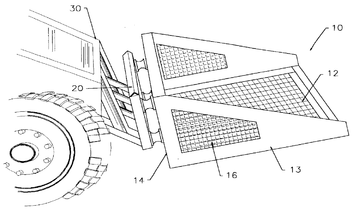
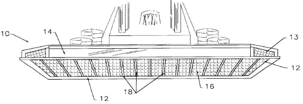
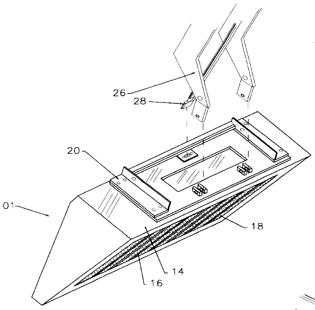
With reference now to the drawings, a new, improved rock screed bucket embodying the principles and concepts of the present invention will be described. A preferred embodiment of the new, improved rock screed bucket 10 is shown in FIG. 1. The new, improved rock screed bucket 10 has a solid rectangular back plate 14 together with framework having a rectangular bottom 12 and a pair of generally triangular shaped side frames 13. The pair of generally triangular shaped side frames 13 and rectangular bottom 12 are joined along their corresponding edges with angle iron. In one embodiment, a screen 16 is attached to the rectangular bottom 12 and to the generally triangular shaped side frames 13 to grade any material that is placed in the new, improved rock screed bucket 10. In another embodiment, the screen 16 is attached to the rectangular bottom 13 and the generally triangular shaped side frames 13 are solid. Only material smaller than the screen mesh can pass through the screen 16.

As be...


PUM


Abstract

The present new, improved rock screed bucket has a solid rectangular back plate together with a framework having a rectangular bottom and a pair of generally triangular shaped sides. The solid rectangular back plate acts as a backstop. The rectangular bottom supports a heavy duty grading screen. A mounting frame is mounted to the rear of the solid rectangular back plate through a plurality of shock absorbing spacers. The conventional arm structures and conventional hydraulic system of a conventional tractor or skid loader connect to the mounting frame. By rapidly moving the conventional arm structure and conventional hydraulic system any material in the rock screed bucket can be shaken and thus screened. In a second embodiment, a hydraulic shaker may be attached to the top of the rock screed bucket to shake the rock screed bucket. The hydraulic shaker is conventional and derives its power from the conventional hydraulic system of the tractor or skid loader.

Description

1. Field of InventionThis invention relates to a new, improved rock screed bucket for use in separating and grading particularized material such as sand, gravel and rock and for connection to conventional arm structure and conventional hydraulic system of a mobile machine such as a tractor or front end loader.2. Description of Prior ArtThe prior art discloses the use of screens in combination with earth moving buckets and the use of screens to separate different substances.U.S. Pat. No. 5,160,034 to Potter teaches a vibrating bucket screen attachment for cleaning beaches mounted on a mobile machine. Potter includes an outer excavating bucket with a sand scooping blade and runners on the outer bucket for supporting the outer bucket relative to the beach and an inner vibrating screen bucket which is resiliently mounted in the excavating bucket and includes a hydraulically operated vibrator. Potter teaches a floor screen portion of the inner bucket being mounted above the bottom sand-e...

Claims


Application Information

Patent Timeline
Patent Type & Authority Patents(United States)
IPC IPC(8): B07B1/28B07B1/46E02F7/06E02F7/00E02F3/40
CPCB07B1/28B07B1/46E02F7/06E02F3/405E02F3/407E02F3/401
Inventor DAVIS, RICHARD D.
Owner DAVIS RICHARD D
Why Eureka
Try Eureka