Vibration damper having oscillating force generating means
- Summary
- Abstract
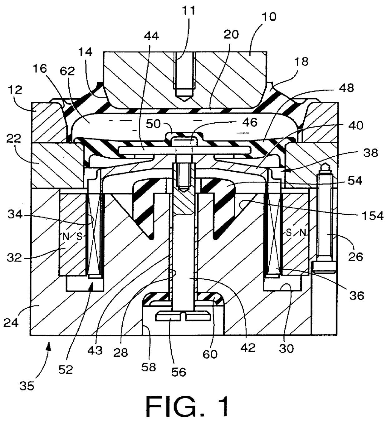
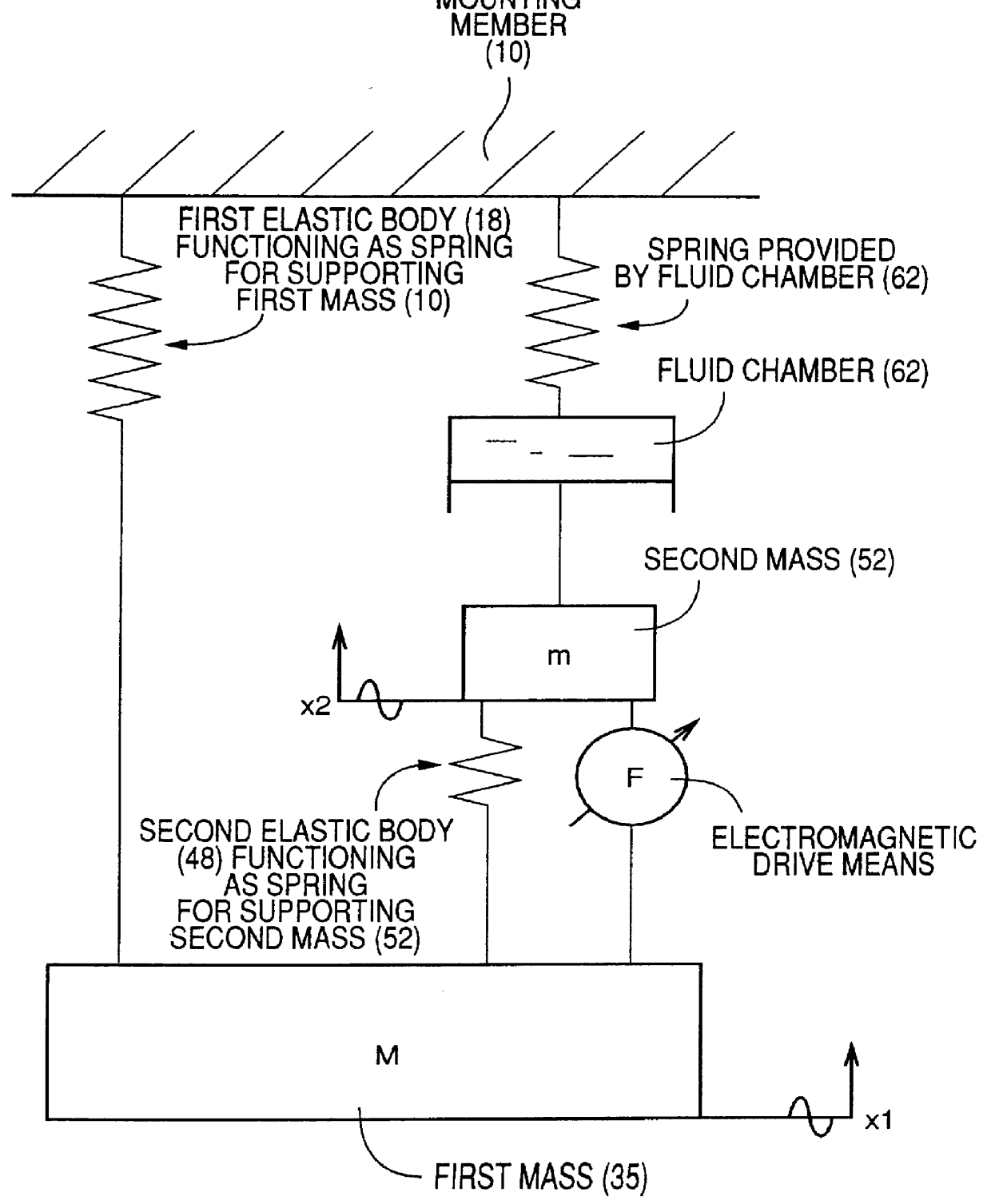
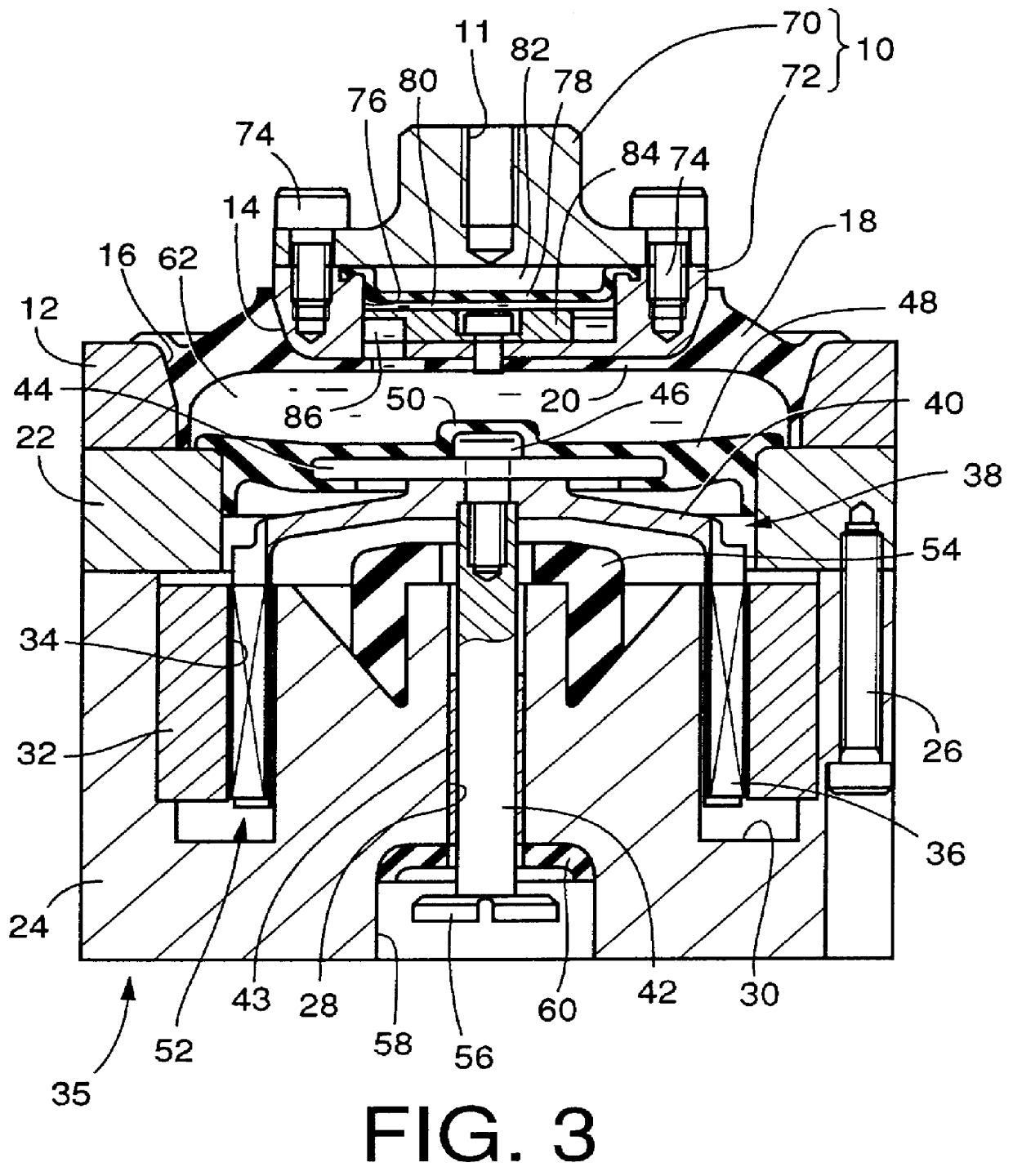
- Description
- Claims
- Application Information
AI Technical Summary
Problems solved by technology
Method used
Image

Examples
Example
As a comparative example 1, a vibration damper was produced which is identical in construction with the vibration damper of the above example, except that the fluid chamber (62) of the damper of the comparative example 1 was not filled with the non-compressible fluid. The frequency characteristics of the oscillating force were measured in this damper of the comparative example 1 under the same conditions as in the above example. The result is also indicated in FIG. 4.
Example
As a comparative example 2, the frequency characteristics of the oscillating force were measured of the electromagnetic drive means per se, which is identical in construction with the electromagnetic drive means of the damper in the above example according to the present invention. Namely, this electromagnetic drive means of the comparative example 2 was obtained by removing, from the vibration damper used in the above example, the integral assembly including the mounting member 10 and connecting member 12 connected to each other by the first elastic body 18. The frequency characteristics of the oscillating force generated between the first mass 35 and the second mass 52 were measured upon energization of the coil 36 by application of the alternating current of 1A. The result is also shown in FIG. 4.
As is apparent from the results of FIG. 4, the vibration damper according to the present invention is capable of applying, to the subject body, the oscillating force several times as lar...
PUM
 Abstract
Description
Claims
Application Information
 - R&D Engineer
- R&D Manager
- IP Professional
- Industry Leading Data Capabilities
- Powerful AI technology
- Patent DNA Extraction
Browse by: Latest US Patents, China's latest patents, Technical Efficacy Thesaurus, Application Domain, Technology Topic.
© 2024 PatSnap. All rights reserved.Legal|Privacy policy|Modern Slavery Act Transparency Statement|Sitemap