Flyweight system

a technology of weight system and belt, which is applied in the direction of gearing control, gearing elements, hoisting equipment, etc., can solve the problems of reducing the life of the belt, slipping of the belt, and tendency to lose power

Inactive Publication Date: 2002-02-12
NOUIS TECH
View PDF5 Cites 26 Cited by
  • Summary
  • Abstract
  • Description
  • Claims
  • Application Information

AI Technical Summary

Benefits of technology

FIG. 2F shows the manner that the present invention would use to place the preferred massive shoulder on head 15C to effect Ski-Doo shoulder 11C.

Problems solved by technology

The undesirable result of the just described belt side force is a tendency to lose power because of belt slippage due to insufficient belt side force while the vehicle is accelerating to near maximum speed.
Especially for larger shift ratios, a significant problem of the prior art has been slipping of the belt because of insufficient primary pulley side force on the belt.
Such insufficiency of side force reduces belt life, wastes fuel, and reduces the performance of the vehicle using a CVT.
Clearly, it would be very difficult, if not impossible, to start an engine while it is connected to an ideal clutch system.
The added complexity, wear, and expense of such a scheme seems undesirable.

Method used


Image

  • Flyweight system
  • Flyweight system
  • Flyweight system

Examples


Embodiment Construction

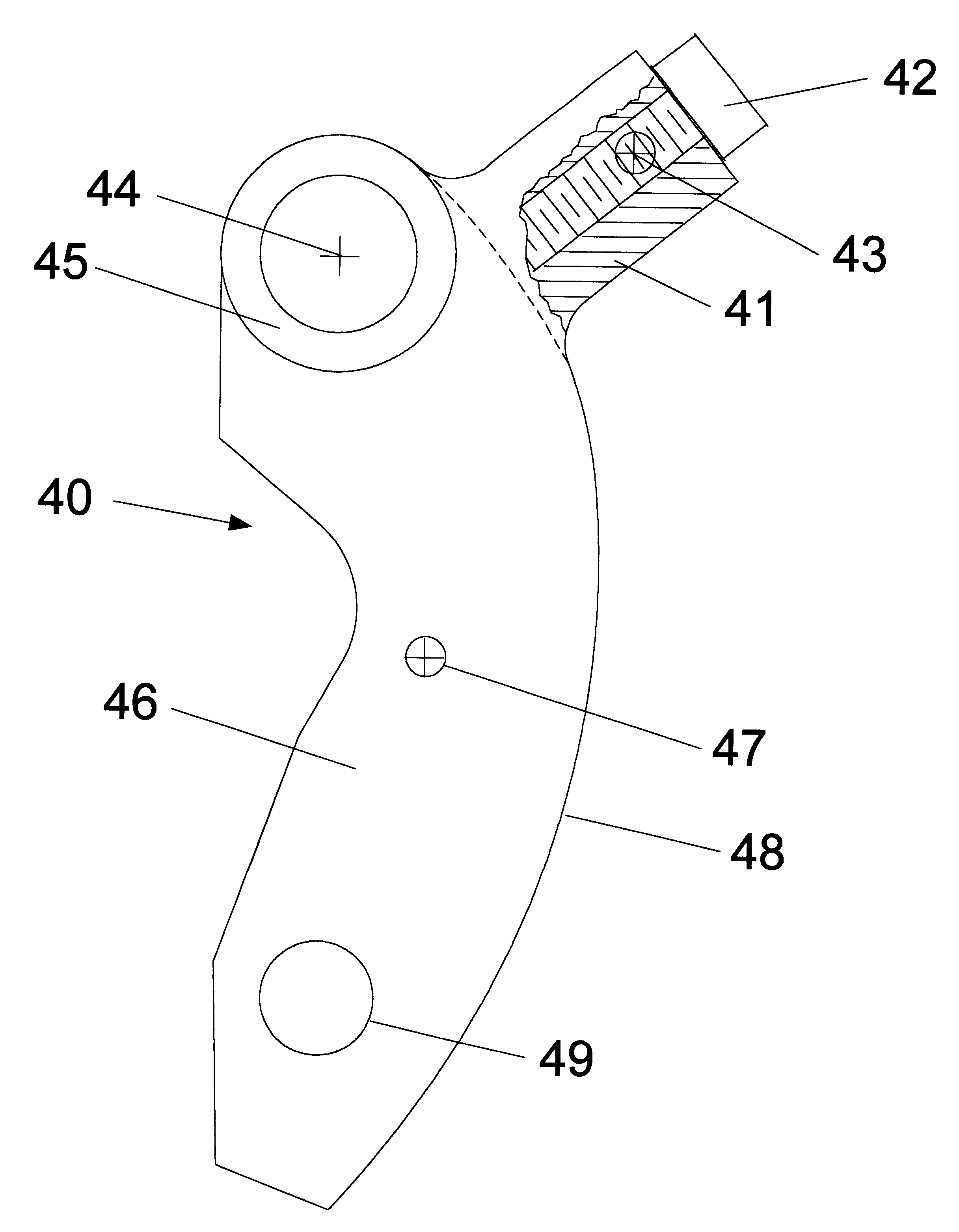
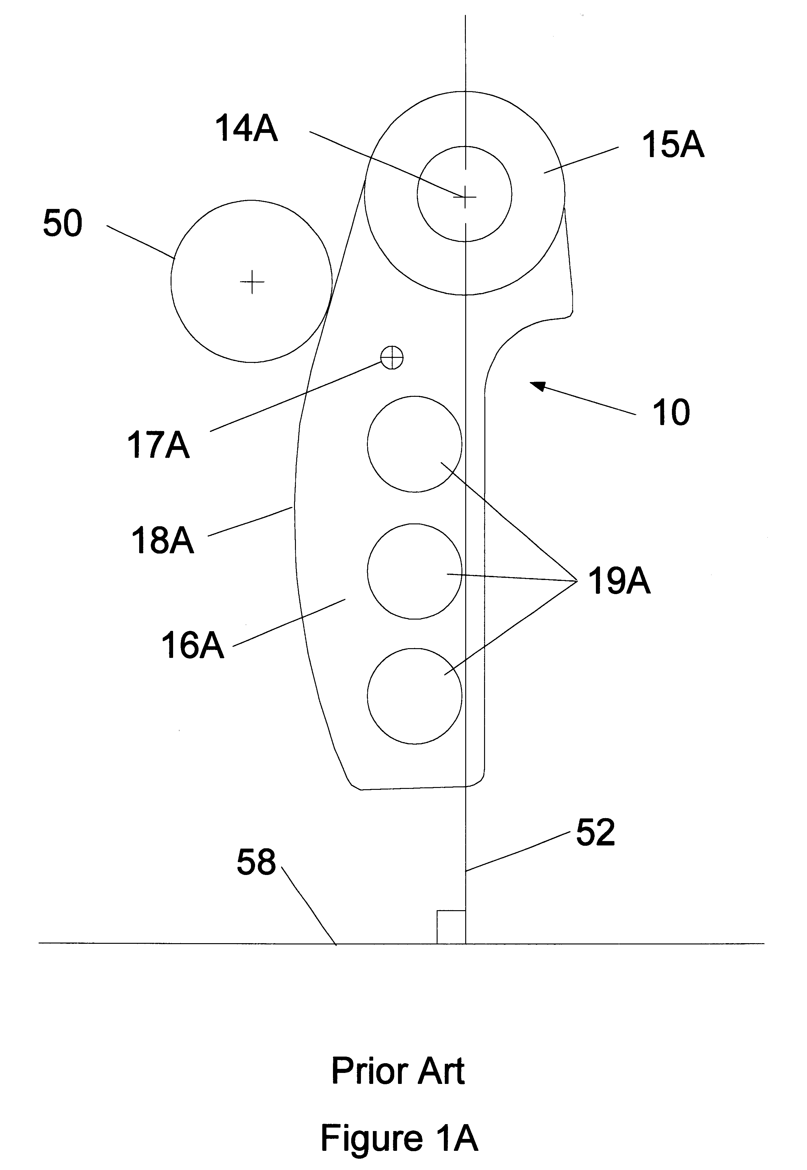
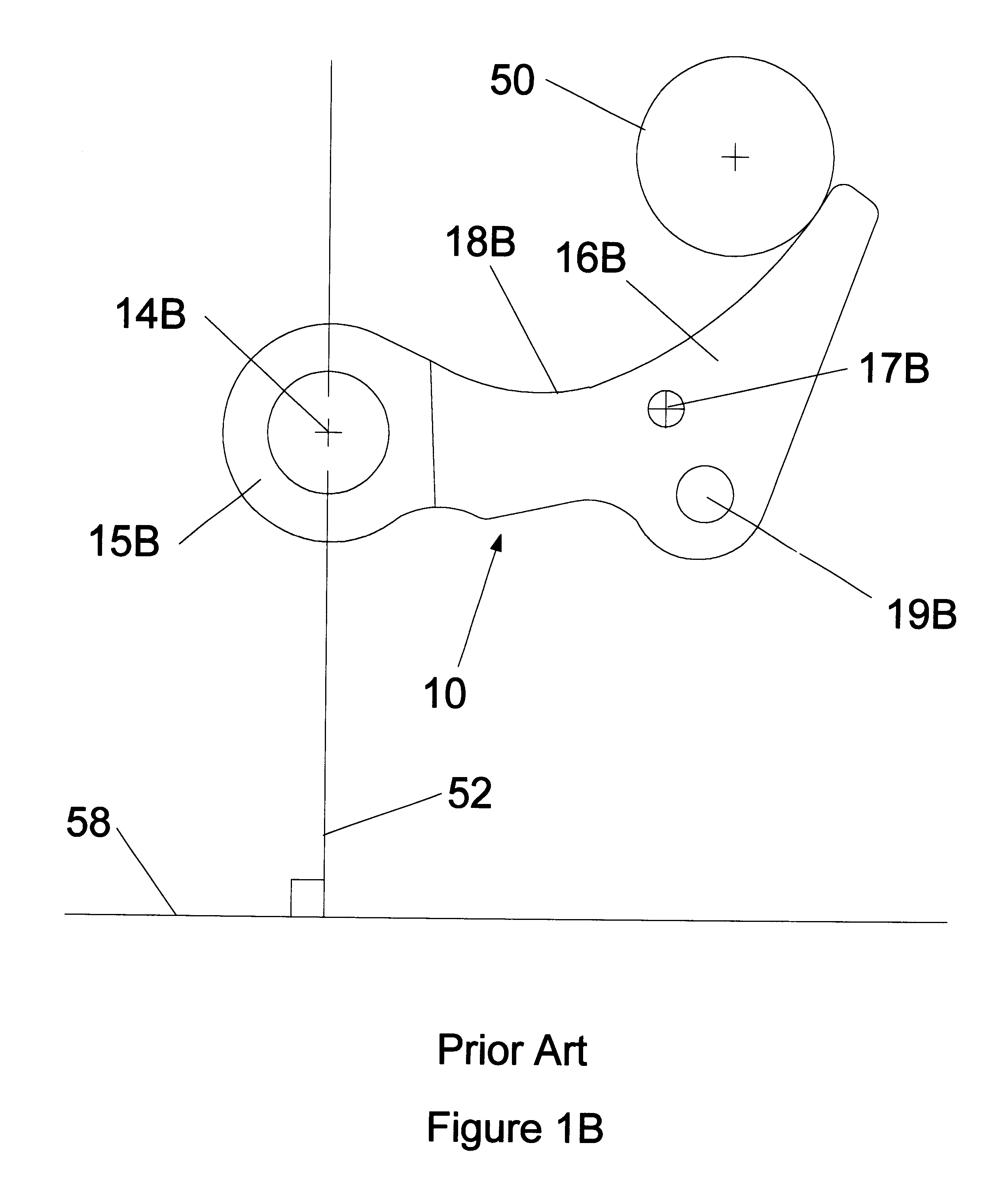
The present invention includes improvements to methods of producing centrifugal force, and thus the side force on the belt of a CVT resulting in reduced or no belt slippage, and includes improvements to flyweights and the means of biasing the flyweights. Preferably, the improved method includes strategically causing an asymmetrical rotational inertia (J) in the vicinity of a flyweight's head.

The practice of the present invention includes supplementing a conventional flyweight with one or more mass concentrations having their COMs more than 10 millimeters from the flyweight's pivot's center in the first, second, and third quadrants. In the third quadrant, supplementing mass concentrations have their COMs more than 10 millimeters from the plumb line. The practice of the present invention also includes supplementing a conventional flyweight with one or more mass concentrations having their COM's more than 10 millimeters from the head and arm of the conventional flyweight. All of these ...


PUM


Abstract

Continuously variable speed drives (CVT) have improved performance over all shift ratios using an improved flyweight (camweight) that enhances power transfer for higher shift ratios (slower vehicle speeds) without compromising efficiency or performance at smaller shift ratios. Prior art CVTs characteristically have some belt slippage, and attendant power waste and excess wear, when operating with higher shift ratios. The prior art deficiency is due to a tendency of the prior art flyweights not to cause sufficient side forces (axial forces) on the belt at higher shift ratios. The present invention preferably supplements conventional flyweights with a massive shoulder that is a supplemental mass concentration placed near the flyweight's center of rotation, and at an obtuse angle from the center-of-mass (COM) of a conventional flyweight, such that the resultant centrifugal forces effect a desirable axial force. Embodiments are disclosed that allow adjusting the degree of improvement. Measurements are presented showing that improvement may be effected at high and moderate shift ratios. The improved flyweight has utility in flyweight using systems not using belts.

Description

The present invention is an improvement, and method of using that improvement, to a family of belt-using, variable power transmission systems. Such systems include an endless belt power transmission system using pulleys, such as cone or tapered-face pulleys, with belt receiving surfaces formed by drive faces on axially movable, coaxially confronting members. Generally, such transmissions are called continuously variable transmissions, which will be referred to herein by the common abbreviation of "CVT." More particularly, the variable power transmission systems using the improvement of the present invention axially move the confronting pulley surfaces in response to the centrifugal force produced by the rotational speed acting on a pivoted weight. The pivoted weight is a cam commonly called, and herein called, a camweight or a flyweight. The improvements of the present invention include improvements to the means of producing the centrifugal force so as to produce a more desirable si...

Claims


Application Information

Patent Timeline
Patent Type & Authority Patents(United States)
IPC IPC(8): F16H61/66F16H63/02F16H63/06F16H61/662F16H55/56
CPCF16H63/067F16H61/66272F16H55/563F16H61/66245F16H61/66268
Inventor NOUIS, RANDY GENENOUIS, CYNTHIA LYNN
Owner NOUIS TECH
Why Eureka
Try Eureka