Fuel injector device for engines

a fuel injector and engine technology, applied in the direction of machine/engine, fuel injector pump, fluid pressure injection control, etc., can solve the problems of degrading mileage, increasing manufacturing cost, and low fuel efficiency

Inactive Publication Date: 2000-05-16
ISUZU MOTORS LTD
View PDF15 Cites 21 Cited by
  • Summary
  • Abstract
  • Description
  • Claims
  • Application Information

AI Technical Summary

Problems solved by technology

The fuel injection device of a type disclosed in Japanease Patent Laid-Open No. 171266/1992 such as shown in FIG. 8 and 9, however, has the drawback that although fuel seems to be not wasted because the three-way valve that opens and closes the exhaust passage closes the supply passage communicating with the balance chamber, the high pressure fuel actually leaks through a sliding clearance in the three-way valve, resulting in lower fuel efficiency than in the two-way valve.
The fuel leakage constitutes a wasted work of the fuel injection pump, degrading the mileage.
This unavoidably increases the size of the actuator (solenoid) that opens the solenoid valve against the force of the spring, which in turn poses such pro...

Method used


Image

  • Fuel injector device for engines
  • Fuel injector device for engines
  • Fuel injector device for engines

Examples


Embodiment Construction

Now, embodiments of this invention will be described by referring to the accompanying drawings.

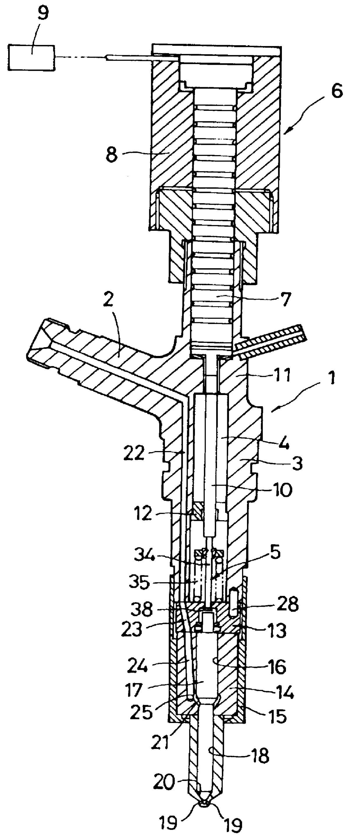
This fuel injection device is applied to a common rail injection system or an accumulator injection system (not shown). Fuel, which is supplied from the fuel injection pump through a common passage or a pressure accumulation chamber (referred to as a common rail), is injected into each combustion chamber in the engine. First, referring to FIG. 1, a body 1 of the fuel injection device is hermetically installed in a hole (not shown) formed in a base such as a cylinder head with a sealing member interposed. The device body 1 has a nozzle hermetically formed at the lower end thereof.

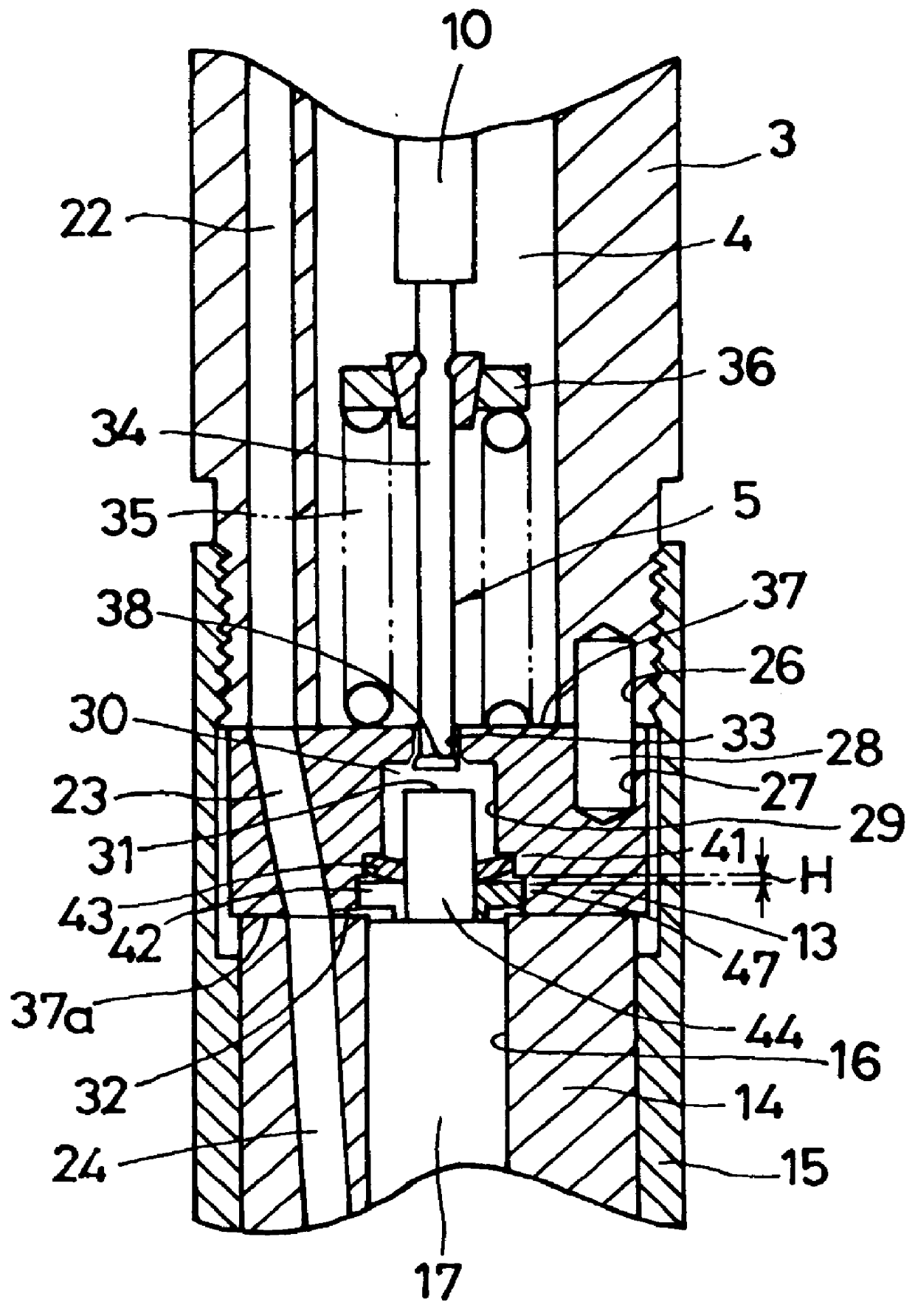
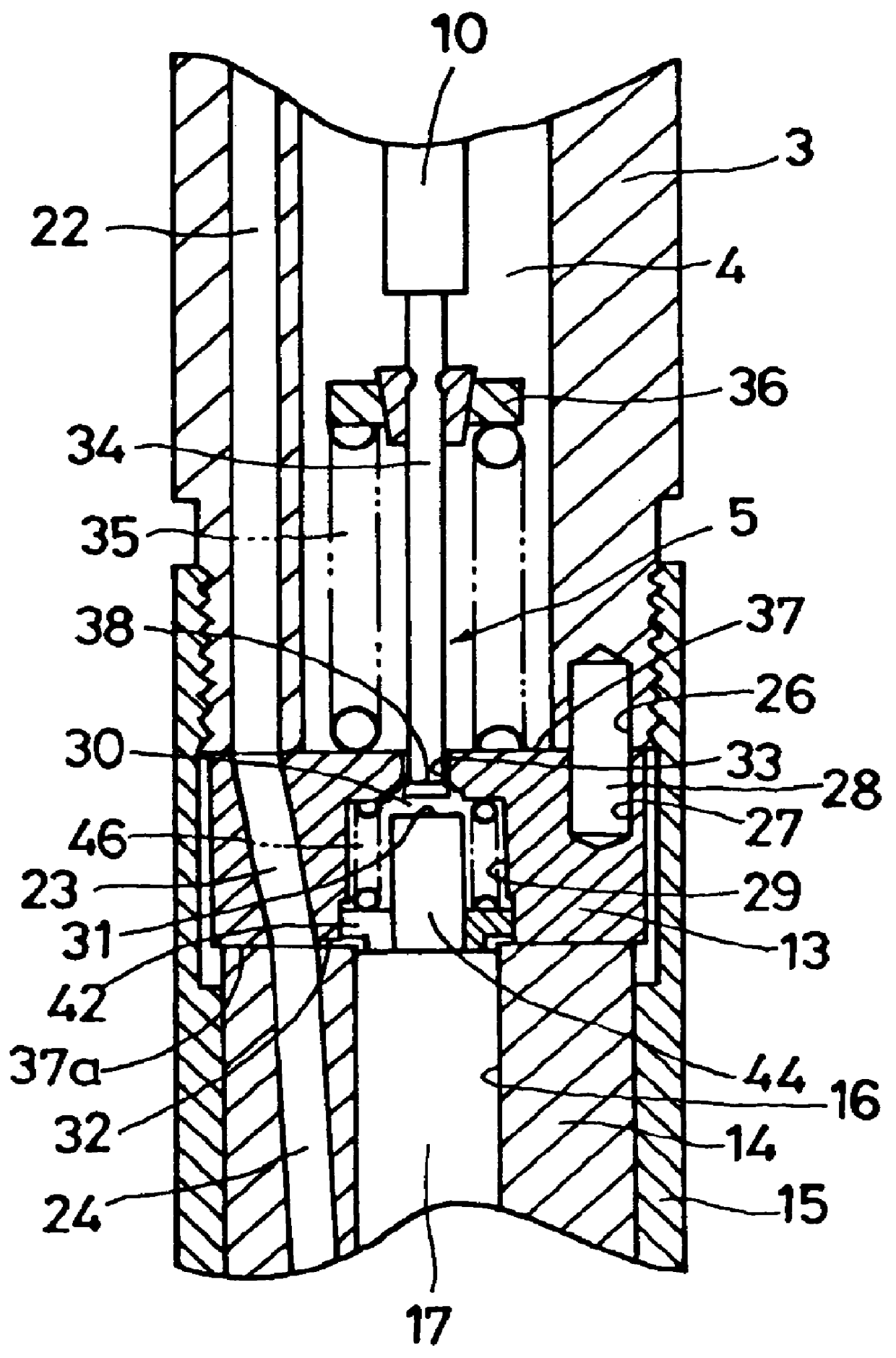
A fuel inlet portion 2 is formed at a shoulder part of the device body 1 and a hollow portion 4 is formed in a central body portion 3 of the device body 1 along the axis. In the hollow portion 4 is installed an open-close valve 5 described later that opens and closes an exhaust passage and is driven by an actuator ...


PUM


Abstract

The fuel injection device of this invention utilizes the fuel pressure in the balance chamber for closing the open-close valve to prevent fuel leakage from the open-close portion. When the open-close valve is opened, the valve stem of the open-close valve piercing through the exhaust passage in the control member moves toward the balance chamber. The valve head opens the port of the exhaust passage on the balance chamber side to lower the fuel pressure in the balance chamber, with the result that the needle valve lifts injecting the fuel. When the open-close valve is closed by the return spring, the fuel pressure in the balance chamber acts on the valve head to urge the open-close valve in the valve closing direction, preventing the leakage of fuel through the open-close valve.

Description

1. Field of the InventionThe present invention relates to a fuel injection device applied to engines such as diesel engines or direct injection type gasoline engines.2. Description of the Prior ArtConventional fuel injection devices that control fuel injection into combustion chambers of engines such as diesel engines include those disclosed in Japanese Patent Laid-Open Nos. 965 / 1991 and 171266 / 1992. These fuel injection devices have a needle valve that opens or closes nozzle holes formed at the front end of an injection nozzle and control the fuel injection by the balance between a force produced by a fuel pressure acting on the needle valve on the nozzle front side in a direction that opens the nozzle holes and a force produced by a fuel pressure in a balance chamber acting in a direction that closes the needle valve.The fuel injection device of a type disclosed in the Japanese Patent Laid-Open No. 171266 / 1992 uses a three-way valve to open and close an exhaust passage that releas...

Claims


Application Information

Patent Timeline
IPC IPC(8): F02M59/00F02M59/46F02M47/02F02M63/00F02M47/00F02M51/00F02M51/06
CPCF02M47/027F02M63/0035F02M63/0026F02M2547/003
Inventor TOKUMARU, TAKESHI
Owner ISUZU MOTORS LTD
Why Eureka
Try Eureka