Device for attaching busbar to a support rail

a technology for supporting rails and busbars, which is applied in the direction of open busbar installations, substation/switching arrangement details, electric cable installations, etc., can solve the problem of not being optimally resolved in connection with known devices

Inactive Publication Date: 2000-05-30
RITTALWERK RUDOLF LOH GMBH & CO KG
View PDF5 Cites 68 Cited by
  • Summary
  • Abstract
  • Description
  • Claims
  • Application Information

AI Technical Summary

Problems solved by technology

This has not been optimally resolved in connection with known devices of the type mentioned above, since one of the desired aspects always was preferred.

Method used


Image

  • Device for attaching busbar to a support rail

Examples


Embodiment Construction

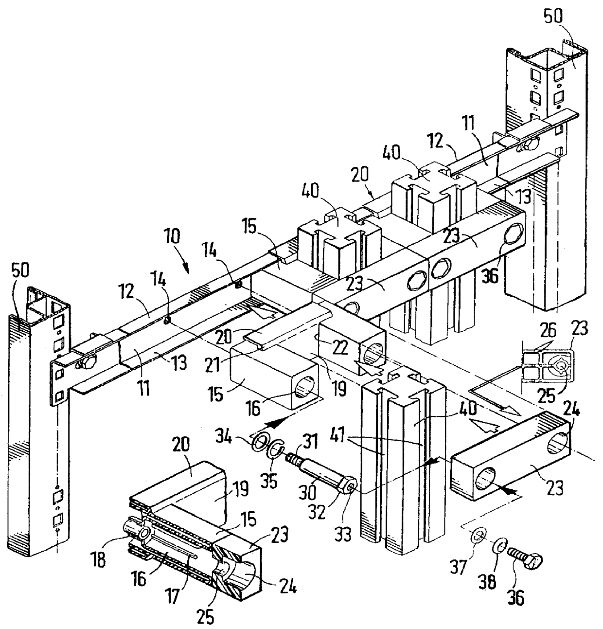
The busbars 40 utilized in the busbar system have a generally square cross section. Continuous T-grooves are cut into exterior longitudinal sides of the busbars 40.

A metal support rail 10 is fastened between two frame legs 50 or mounting rails of a switchgear cabinet, which is designed in a U-shape with a base leg 11 and lateral legs 12 and 13 and which faces the busbars 40, which are to be fastened, with the open side. Threaded bores 14 are cut into the base leg 11 in order to be able to fasten post-shaped supports 15 at desired distances. The supports 15 are made from plastic injection-molded parts and have a square exterior cross section which is selected so that the supports 15 can be placed, fixed against relative twisting, between the lateral legs 12 and 13 of the support rail 10. As the partial section shows, the support 15 is designed as a hollow body which can be unmolded in the direction toward the support rail 10, which has a screw receptacle 16 ending in a fastening slee...


PUM


Abstract

A device for attaching busbars of square or rectangular cross section on a support rail using electrically non-conducting support elements, which can be connected with the support rail and form a busbar receptacle adapted to the cross section of the busbar. With a simple fastener, assembly is considerably simplified because two post-shaped supports per busbar can be attached as support elements on the support rail, wherein spacing between the supports is matched to the width of the busbar and a height is matched to the thickness of the busbar. A base plate is arranged between the two supports, which insulates the busbar receptacle against the support rail and which is captively held between the holders. The ends of the supports facing away from the support rail can be closed by a strip.

Description

1. Field of the InventionThis invention relates to a device for attaching busbars of square or rectangular cross section on a support rail by using electrically non-conducting support elements, which can be connected with the support rail and form a busbar receptacle adapted to the cross section of the busbar.2. Description of Prior ArtIt is important to be able to mount busbars in an insulated manner, very rapidly and definitely on the support rail, which is made of metal. Thus, it should be possible to employ simple support elements. This has not been optimally resolved in connection with known devices of the type mentioned above, since one of the desired aspects always was preferred.It is one object of this invention to create a device of the type mentioned above, which permits a quick attachment of the busbars to the support rail by simple support and fastening elements, and which in the process assures a definite insulation against the support rail.In accordance with this inven...

Claims


Application Information

Patent Timeline
Patent Type & Authority Patents(United States)
IPC IPC(8): H02B1/20H02G5/00H02G5/02
CPCH02G5/025H02B1/20
Inventor WAGENER, HANSZACHRAI, JURGEN
Owner RITTALWERK RUDOLF LOH GMBH & CO KG
Why Eureka
Try Eureka