
Electric source system of track traffic locomotive and control method of electric source system

A rail transit and power system technology, applied in power lines, vehicle components, transportation and packaging, etc., can solve the problems of power grid voltage fluctuations, large energy losses, and can only be towed away

Active Publication Date: 2016-03-16
惠州美亿瑞创电气设备有限公司
View PDF7 Cites 52 Cited by
  • Summary
  • Abstract
  • Description
  • Claims
  • Application Information

AI Technical Summary

Problems solved by technology

[0002] Urban rail transit locomotives have the characteristics of frequent start and stop. During the start-up process, the locomotive needs a large traction power for a short time, which will cause large fluctuations in the nearby power grid voltage; when the locomotive stops at the station, the brakes are mostly mechanical Energy feedback in combination with dynamic or mechanical braking has low energy utilization, and mechanical braking will generate a lot of heat and noise. If resistance braking is used, the energy loss will be large; moreover, there is no emergency traction measures at present, which is easy After an emergency, the service on the line will be suspended on a large scale, and if there is a failure, it can only be towed away

Method used


Image

  • Electric source system of track traffic locomotive and control method of electric source system

Examples


Embodiment

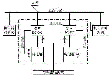
[0026] Such as figure 1 As shown, a rail transit locomotive power supply system includes a DC bus connected to the urban power grid system. The DC bus directly supplies power to the locomotive. The DC load of the locomotive is connected to the DC bus and is directly powered by the DC bus. A two-way power supply release absorbing device is set between them. The two-way power release absorbing device can provide part of the traction power when the locomotive is started, and smooth the grid waveform; absorb the braking energy during braking to improve energy utilization efficiency; it can provide traction power to run the rail locomotive at a low speed for a certain distance, so that Avoid rail locomotives from occupying the line and provide an effective method for emergency treatment.

[0027] The bidirectional power release and absorbing device includes two bidirectional DC / DCs connected between the DC bus and the DC load of the locomotive, and is used to monitor the voltage o...


PUM


Abstract

The invention provides an electric source system of a track traffic locomotive. The electric source system comprises a direct current busbar for directly providing electricity for the locomotive, and a locomotive direct current load connected with the direct current busbar, wherein a bidirectional electric source release and absorption device is arranged between the direct current busbar and the locomotive direct current load. When the track traffic locomotive is started and braked, the electric source system has the effect of smoothing the voltages of an electrical network, and the influence of the track traffic locomotive on the electrical network is reduced; when the track traffic locomotive is braked, energy generated in the braking process of the track traffic locomotive can be recovered, so that the utilization efficiency of energy resources is improved, and the purposes of energy conservation and environmental protection are achieved; when the track traffic locomotive has electricity supply failure due to the locomotive or the electrical network, emergency towing can be started, so that the locomotive is towed to a safe position, the situation that the locomotive occupies lines is avoided, the operation efficiency is improved, and urgent failure handling capacity is improved. The scheme adopted by the electric source system is upgraded based on an original standby electric source, so that space usage is small, and the technology cost is reduced; according to the residual capacity of current batteries, an emergency towing scheme can be automatically made, and the control is more intelligentized.

Description

technical field [0001] The invention relates to the field of power supply management of rail transit locomotives, and more specifically, to a rail transit locomotive power supply system and a control method thereof. Background technique [0002] Urban rail transit locomotives have the characteristics of frequent start and stop. During the start-up process, the locomotive needs a large traction power for a short time, which will cause large fluctuations in the nearby power grid voltage; when the locomotive stops at the station, the brakes are mostly mechanical Energy feedback in combination with mechanical braking or mechanical braking has a low energy utilization rate, and mechanical braking will generate a lot of heat and noise. If resistance braking is used, the energy loss will be large; After an emergency occurs, the service on the line will be suspended on a large scale, and the fault can only be towed away. Contents of the invention [0003] In view of this, the tec...

Claims


Application Information

Patent Timeline
IPC IPC(8): B60M3/02
CPCB60M3/02
Inventor 刘飞文锋龚敏明李少林
Owner 惠州美亿瑞创电气设备有限公司
Learn More