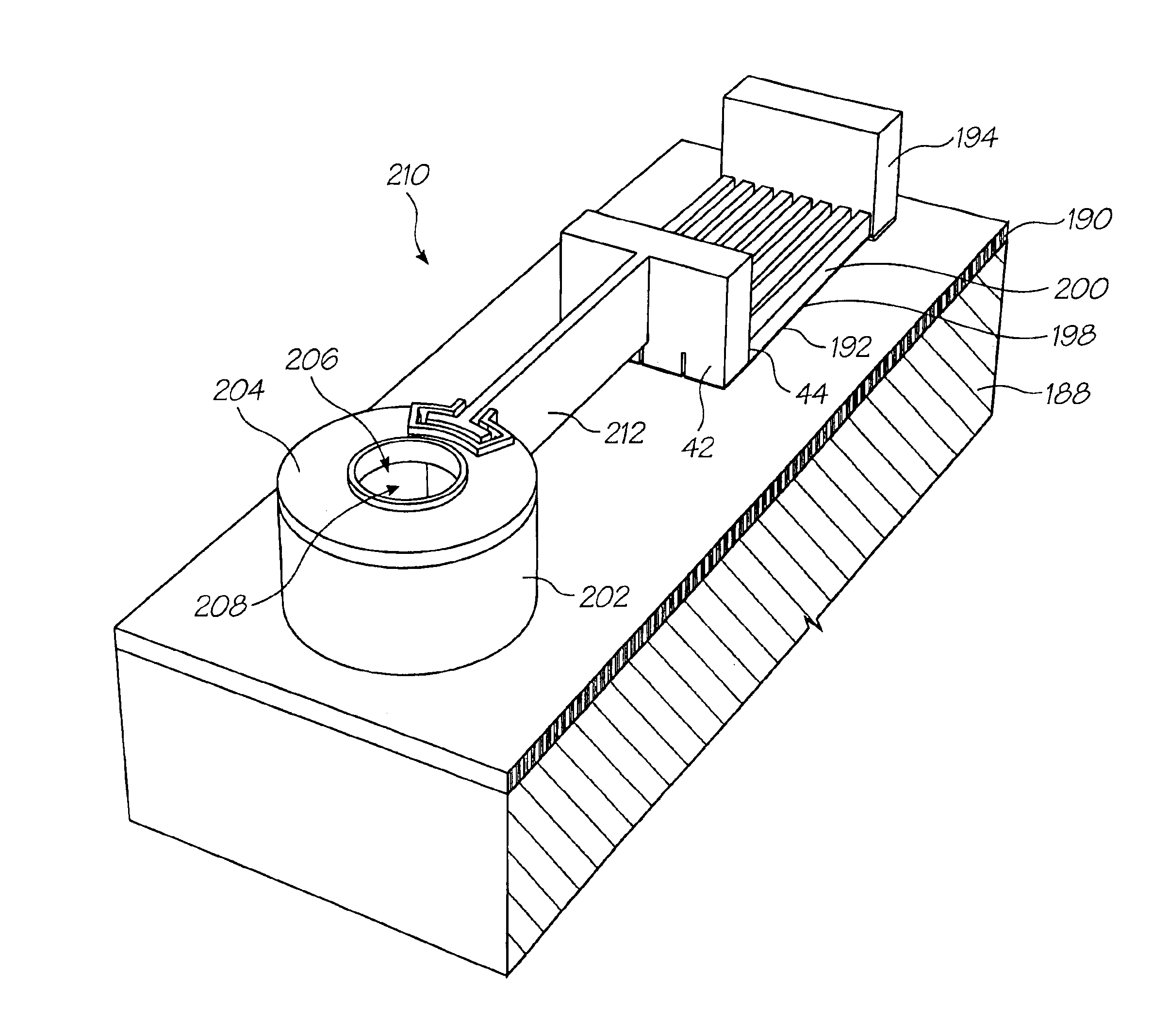
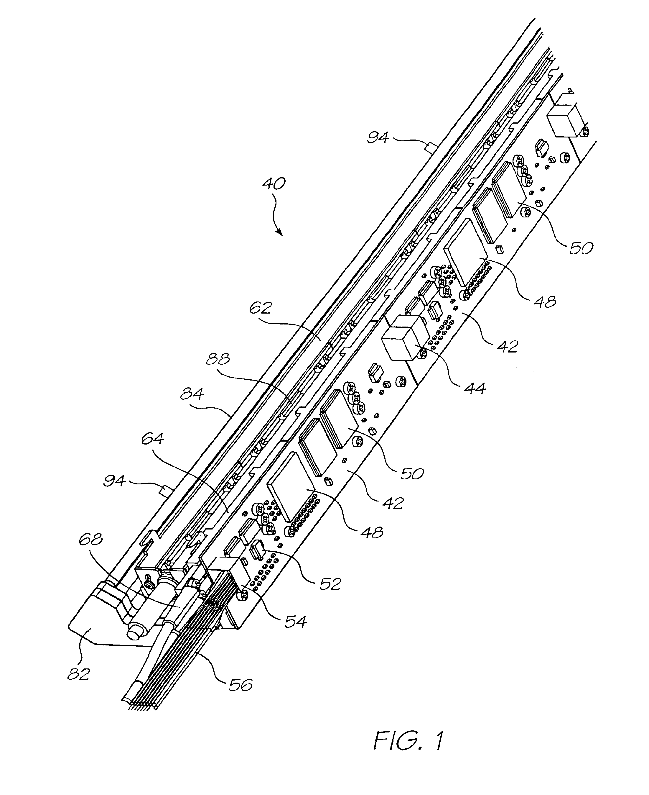
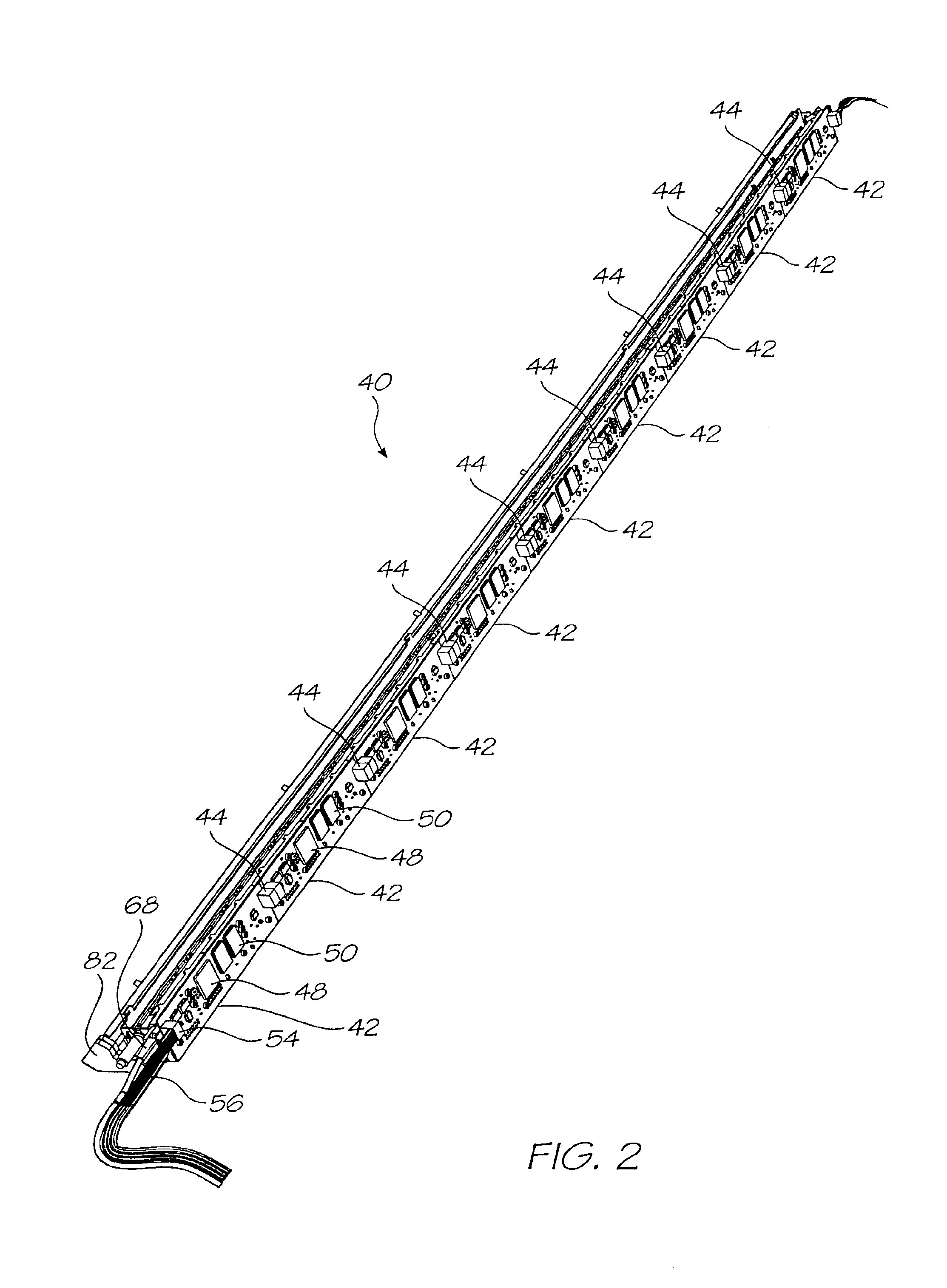
Printing mechanism for a wide format pagewidth inkjet printer

a printing mechanism and wide-format technology, applied in the field of wide-format page-width inkjet printers, can solve the problems of inability inability to use a traversing printhead in an attempt to achieve high-speed printing, and excessive heat build-up and energy consumption of the printer

Inactive Publication Date: 2005-07-12
MEMJET TECH LTD +1
View PDF90 Cites 49 Cited by
  • Summary
  • Abstract
  • Description
  • Claims
  • Application Information

AI Technical Summary

Problems solved by technology

Applicant believes that these printers suffer from inherent disadvantages, particularly when attempts are made to utilize the design of such printers in order to achieve faster printing speeds at high resolutions.
Central to the problem of achieving high printing speeds is the ability to achieve a printhead that is capable of generating the necessary number of ink dots at a suitable rate.
It follows that it is undesirable for a traversing printhead to be used in an attempt to achieve high print speeds and that a single printhead incorporating a suitable number of inkjet nozzles is required.
These suffer from excessive heat build up and energy consumption and have therefore been found by the applicant to not be suitable for use in a pagewidth configuration.
The Applicant has been faced with a number of difficulties in order to achieve the effective use of such printhead chips in wide format printers.
One particular difficulty identified by the Applicant is the effective control of a number of such printhead chips to achieve accurate printing.
Another difficulty that faces the manufacturers of wide format printers are the problems associated with heat build up.
This can often result in the necessity for expensive heat extraction devices that add to the complexity of the printer.

Method used


Image

  • Printing mechanism for a wide format pagewidth inkjet printer
  • Printing mechanism for a wide format pagewidth inkjet printer
  • Printing mechanism for a wide format pagewidth inkjet printer

Examples


Embodiment Construction

[0052]In FIG. 4, reference numeral 10 generally indicates a printer, in accordance with the invention.

[0053]The printer 10 has a support structure 12 that supports a print assembly 14, also in accordance with the invention, above a substrate. The support structure 12 includes a pair of spaced feet 16 and a leg 18 extending from each foot 16. The print assembly 14 is mounted on the legs 18 to span the legs 18.

[0054]A media tray 20 is positioned between the legs 18. The media tray 20 is configured to store suitable print media, such as paper 22.

[0055]The paper 22 is fed from a media feed mechanism in the form of a media roll 166 through the print assembly 14 and on to a take up spool 24. An electronics enclosure 26 is also positioned between the legs 18 to enclose various electronic components that are described below.

[0056]The print assembly 14 includes a lid 28, with a handle 30, and a front cover 32. The lid 28 and front cover 32 are positioned between a pair of end moldings 34.

[00...


PUM


Abstract

A printing mechanism includes an elongate support structure. A pair of busbars is mounted on the support structure. A plurality of printed circuit boards is mounted on the support structure to be electrically connected to the busbars. Each printed circuit board includes print engine control circuitry that is configured to control operation of a number of printhead chips. A plurality of ink distribution structures is mounted on the support structure and connectable to a supply of ink. A plurality of printhead modules is mounted on respective ink distribution structures. Each printhead module has a carrier and a printhead chip positioned on the carrier. Each printhead chip has a plurality of nozzle arrangements that are positioned on a wafer substrate. Each nozzle arrangement incorporates a micro-electromechanical actuator for ejecting ink from a nozzle chamber and is mounted on a respective ink distribution assembly. A number of the printhead chips are connected to the print engine control circuitry such that each nozzle arrangement can receive data signals from the print engine control circuitry.

Description

REFERENCED PATENT APPLICATIONS[0001]This is a Continuation Application of U.S. Ser. No. 10 / 120,351 filed on Apr. 12, 2002 now U.S. Pat. No. 6,672,706.[0002]This application is a continuation-in-part application of U.S. application Ser. No. 09 / 112,767 filed Jul. 10, 1998, now U.S. Pat. No. 6,416,167. The following United States applications and patents are hereby incorporated by reference:[0003]6,227,6526,213,5886,213,5896,231,1636,247,7956,394,5816,244,6916,257,7046,416,1686,220,6946,257,7056,247,7946,234,6106,247,7936,264,3066,241,3426,247,7926,264,3076,254,2206,234,6116,302,5286,283,5826,239,8216,338,5476,247,7966,390,6036,362,8436,293,6536,312,1076,227,6536,234,6096,238,0406,188,4156,227,6546,209,9896,247,7916,336,7106,217,1536,416,1676,243,1136,583,2816,247,7906,260,9536,267,4696,273,5446,309,0486,420,1966,443,5586,439,6896,378,9896,406,1296,505,9166,457,8096,457,8126,428,1336,362,868,6,443,55509 / 422,89309 / 113,122,09 / 693,703STATEMENT REGARDING FEDERALLY SPONSORED RESEARCH OR DEV...

Claims


Application Information

Patent Timeline
Patent Type & Authority Patents(United States)
IPC IPC(8): B41J15/04B41J2/14B41J11/70B41J2/145B41J2/155B41J2/175B41J2/16B41J3/42G06F1/16G06K1/00G06K1/12G07F7/12G07F7/08G06K19/06G06K7/14H04N1/21H04N5/225H04N5/262B41J2/165B41J3/44
CPCB41J2/14427B41J2/155B41J2/1623B41J2/1626B41J2/1628B41J2/1629B41J2/1631B41J2/1632B41J2/1635B41J2/1637B41J2/1639B41J2/1642B41J2/1643B41J2/1645B41J2/1646B41J2/1648B41J2/17503B41J2/17513B41J2/17596B41J3/445B41J11/70B41J15/04G06K1/121G06K7/14G06K7/1417G06K19/06037H04N5/225H04N5/2628B41J2/16585B41J2002/041B41J2202/21B42D2035/34H04N23/00
Inventor SILVERBROOK, KIA
Owner MEMJET TECH LTD
Why Eureka
Try Eureka