Air-conditioning apparatus

a technology of air-conditioning apparatus and air-conditioning evaporator, which is applied in the direction of domestic cooling apparatus, lighting and heating apparatus, defrosting, etc., can solve the problems of insufficient quantity of air blown toward the passenger compartment, deterioration of the drain performance of condensed water, and disturbance of the flow of air through the evaporator

Inactive Publication Date: 2000-06-06
DENSO CORP
View PDF17 Cites 13 Cited by
  • Summary
  • Abstract
  • Description
  • Claims
  • Application Information

AI Technical Summary

Problems solved by technology

Therefore, the condensed water is blown off to deteriorate the drain performance of the condensed water.
Further, because the drain guide members are located below the core portion, the flow of air passing through the evaporator is disturbed.
Therefore, the quantity of air blown toward a passenger compartment is insufficient when a large quantity of air is needed during a hot summer season.
Because the partition member extends in the arrangement direction of the drain guide member to cover the drain guide member, it becomes hard that air hits against the lower end side of the inclined bottom surface of the cooling heat exchanger, where the condensed water gathers.

Method used


Image

  • Air-conditioning apparatus
  • Air-conditioning apparatus
  • Air-conditioning apparatus

Examples


first embodiment

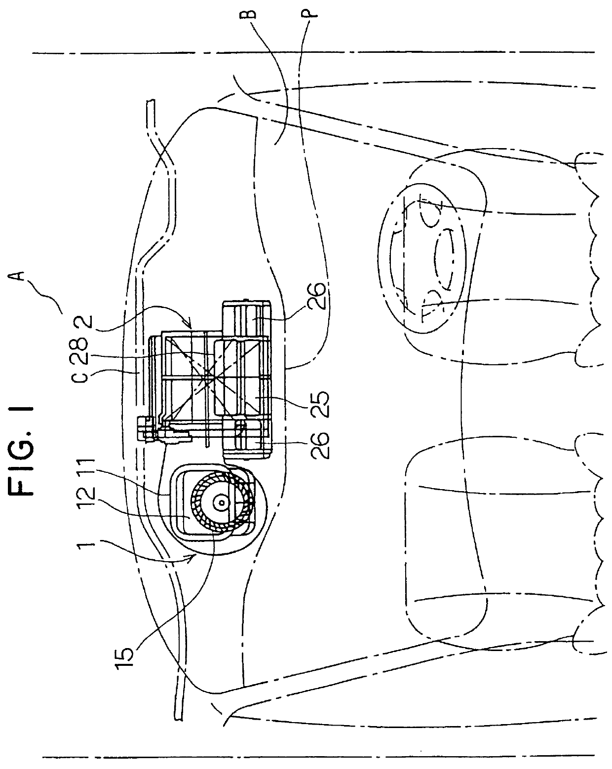
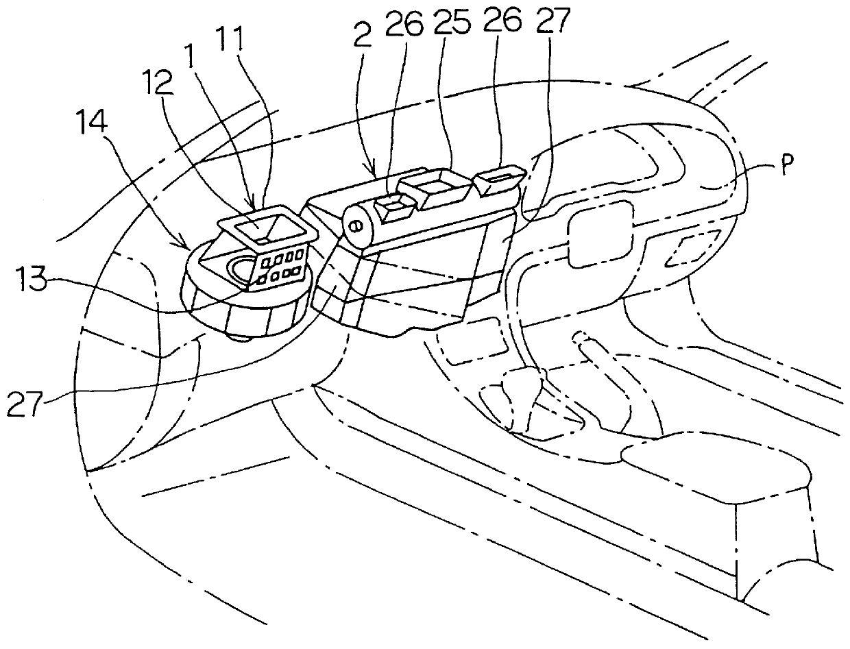
In FIGS. 1 and 2, an engine compartment A and a passenger compartment B are separated by a partition plate C (e.g., a fire wall produced of an iron plate). A blower unit 1 of an air-conditioning apparatus is mounted in the passenger compartment B to be shifted in a width direction of the vehicle from a central part of an instrument panel P. In the first embodiment, the blower unit 1 is shifted to the left side in the width direction of the vehicle.

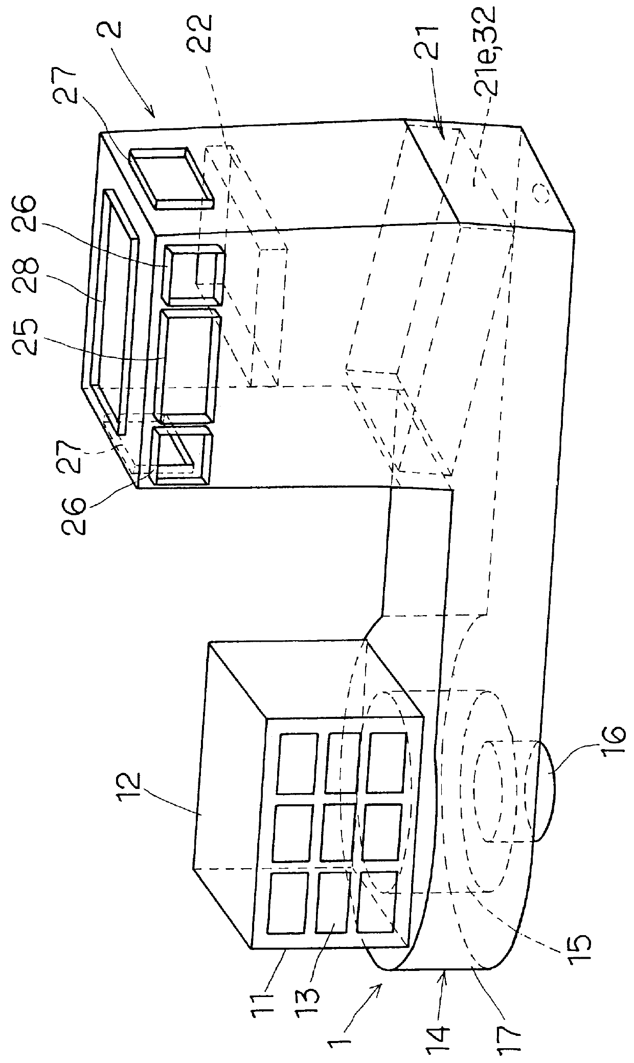
The blower unit 1 has an inside-outside air changeover box 11 in an upper part, for changing over between inside air (i.e., air inside the passenger compartment) and outside air (i.e., air outside the passenger compartment) to be introduced therein. The inside-outside air changeover box 11 is provided with an outside air inlet 12 and an inside air inlet 13, and the outside air inlet 12 and the inside air inlet 13 are opened and closed by an inside-outside air changeover door.

Under the inside-outside air changeover box 11, a blower 14 is di...

second embodiment

The drain guide member 33b' of the second embodiment is formed in a plate-like uninterruptedly extending for the entire range in the longitudinal direction of the tank portion 21e. Therefore, air blown by the blower 14 becomes hard to hit against lower end side of the drain guide member 33b, where the condensed water flows down. Therefore, the condensed water can be rapidly guided without being affected by the air flow, and drips to the bottom surface 30a of the lower casing 30. Consequently, the condensed-water draining efficiency can be improved.

Further, second embodiment, since the lower space 50 is divided by the drain guide member 33' into the air-blown space 50a and the drain space 50b, it is possible to fully prevent the air from hitting against the lower end portion 32 of the inclined evaporator 21, where the condensed water gathers. Thus, the condensed water that has been gathered at the lower end portion 32 of the evaporator 21 can be rapidly dripped entirely without being...

third embodiment

In the third embodiment, the drain guide member 33b' is disposed to contact the boundary V. Therefore, the condensed water dripped from the boundary V flows downwardly along the outside surface (at right and left surfaces in FIG. 12) of the drain guide member 33b'. Consequently, the condensed water that flows along the drain guide member 33b' comes to the bottom surface 30a of the lower casing 30, then flows smoothly along the inclined bottom surface 30a toward the condensed-water drain pipe 29, to be discharged at the outside of the passenger compartment. It is, therefore, possible to decrease the vertical size of the air-conditioning apparatus and also to sufficiently guide the condensed water downwardly by the drain guide member 33b'.

A fourth preferred embodiment of the present invention will be now described.

In the fourth embodiment, as shown in FIG. 13, the partition member 33a which prevents air from striking against the drain guide member 33b' in the third embodiment is provi...


PUM


Abstract

In an air conditioning apparatus, an evaporator is disposed in an air-conditioning case to be inclined relative to a horizontal direction and to form a lower space below the evaporator. Air flows through the evaporator from a lower side toward an upper side thereof in the air-conditioning case. The lower space is partitioned by a partition member into an air-blown space and a drain space, and a drain guide member is disposed in the drain space to approximately contact a lower end portion of the inclined evaporator, where condensed water is gathered. Therefore, it can prevent air from hitting from below against the lower end portion of the evaporator. Consequently, the condensed water that has been gathered at the lower end portion of the inclined evaporator can be discharged rapidly along the drain guide member without being affected by the flow of air, and drips to a bottom surface of the air-conditioning case. Thus, draining-efficiency of condensed water generated on the evaporator can be improved effectively.

Description

1. Field of the Invention:The present invention relates to an air-conditioning apparatus in which a cooling heat exchanger is inclined so that air flows upwardly in the cooling heat exchanger from a lower side thereof.2. Description of Related Art:Conventionally, in an air-conditioning apparatus for a vehicle described in U.S. Pat. No. 5,755,107, an evaporator (i.e., cooling heat exchanger) is inclined and air flows through the evaporator upwardly from a lower side, to reduce a size of an air-conditioning unit. In the conventional apparatus, a plurality of drain guide members for draining condensed water generated on the evaporator are provided to approximately contact an outside surface of a core portion of the evaporator.In the conventional air-conditioning apparatus, because air flows upwardly from below in the evaporator, condensed water does not directly drop with its own weight, but flows down along the surface of the evaporator and gathers at a lower end portion of the inclin...

Claims


Application Information

Patent Timeline
Patent Type & Authority Patents(United States)
IPC IPC(8): B60H1/00B60H1/32F28D1/03
CPCB60H1/00028F28D1/0333B60H1/3233B60H2001/00107
Inventor ITO, KOICHISAIDA, KAZUNORITAHARA, HIROMISUWA, KENJI
Owner DENSO CORP
Why Eureka
Try Eureka