Sealing unit for a fuel pressure sensor

Inactive Publication Date: 2000-06-06
ROBERT BOSCH GMBH
View PDF15 Cites 23 Cited by
  • Summary
  • Abstract
  • Description
  • Claims
  • Application Information

AI Technical Summary

Problems solved by technology

A number of difficulties arise in connection with this.
The threaded bores are often let into the fuel carrying component from the side or even from underneath so that the insertion of the sealing washer is difficult simply because of gravity.
Also, sometimes the threaded bores are partially or completely impossible to see into because they are blocked from view by components disposed in front of them, so that the position of the sealing washer before the insertion of the fuel pressure sensor cannot be optically controlled without some means of assistance.
Therefore an off-center or tilted seating of the sealing washer cannot be detected.
Consequentl

Method used


Image

  • Sealing unit for a fuel pressure sensor
  • Sealing unit for a fuel pressure sensor

Examples


Embodiment Construction

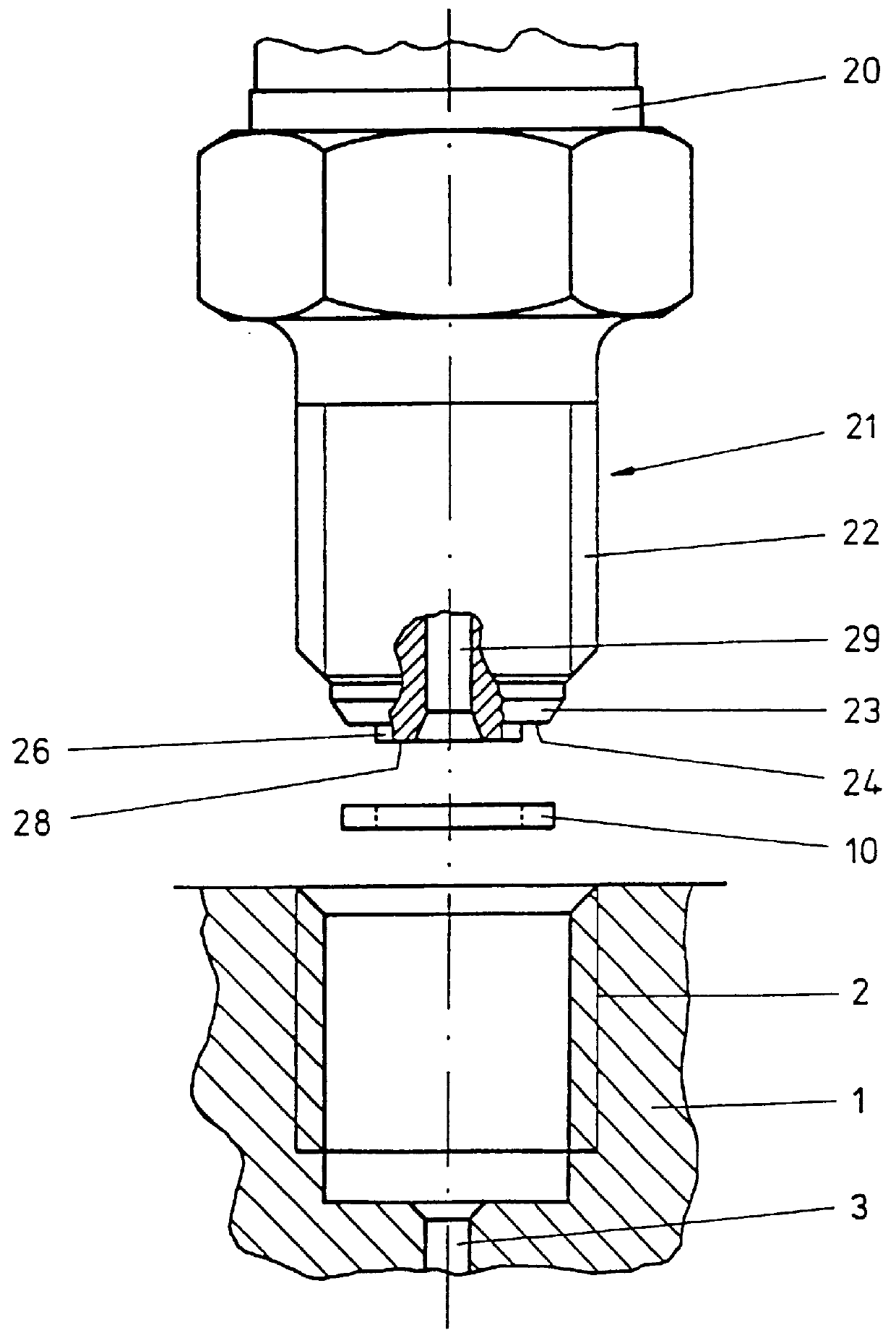
FIG. 1 shows the threaded bolt-shaped end (21) of a fuel pressure sensor (20), a sealing washer (10) and a threaded bore (2) for receiving the fuel pressure sensor (20) in a pressure fluid carrying component (1). The components here are represented in a disassembled state.

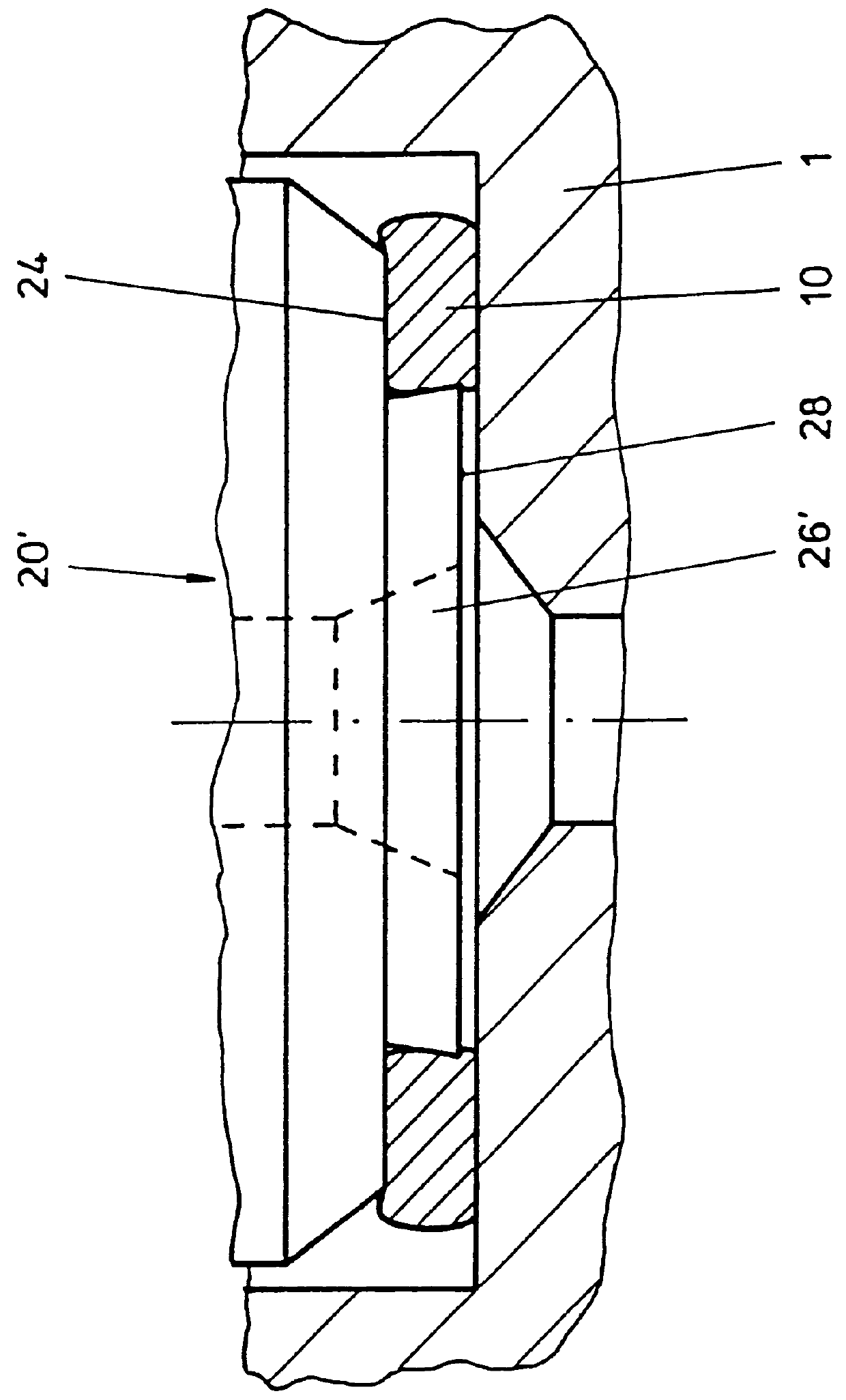
The outer contour of the threaded bolt-shaped end (21) includes a threaded section (22), a bearing section (23) adjoining this, and a centering pin (26) formed onto this bearing section. The bearing section (23) has a cylindrical outer contour whose diameter is smaller than the core diameter of the thread (22). The cylindrical outer contour transitions into an annular end face (24) via a chamfer. This end face (24) is used as the sensor end sealing face. In FIG. 1, the centering pin (26) likewise has a cylindrical outer contour, whose diameter is slightly larger than the inner diameter of the sealing washer (10). The centering pin (26) ends in an end face (28). The length of the centering pin (26) is shorter than t...


PUM


Abstract

PCT No. PCT/DE96/01420 Sec. 371 Date Jun. 25, 1997 Sec. 102(e) Date Jun. 25, 1997 PCT Filed Jul. 31, 1996 PCT Pub. No. WO97/23771 PCT Pub. Date Jul. 3, 1997The invention relates to a sealing unit for a fuel pressure sensor for sealing an at least virtually flat sealing joint between the sensor and a component that carries it via a screw connection, wherein a round sealing washer with a central bore is disposed between the threaded bolt-shaped end of the sensor housing with its central sensor bore and the bottom of the threaded bore of the component with its central pressure fluid opening. A pin is formed onto the threaded bolt-shaped end of the sensor housing, which pin centers the sealing washer, fixing it in a positive and/or frictional, non-positive manner, and rises above an end face that serves as a bearing surface for the sealing washer. The pin ends in an end face and has a length that is shorter than the thickness of the sealing washer. A sealing unit is produced that assures a reliable sealing function and permits a simple installation and disassembly of the sealing washer while reclaiming the sealing washer in a sealing position.

Description

PRIOR ARTThe invention is based on a sealing unit for a fuel pressure sensor.As a rule, sealing units of this kind constitute a fuel pressure sensor in combination with a sealing washer. Both parts are separate from each other. When the fuel pressure sensor is installed in a corresponding threaded bore of a fuel carrying component, the sealing washer is first inserted into the bore. A number of difficulties arise in connection with this. The threaded bores are often let into the fuel carrying component from the side or even from underneath so that the insertion of the sealing washer is difficult simply because of gravity. Also, sometimes the threaded bores are partially or completely impossible to see into because they are blocked from view by components disposed in front of them, so that the position of the sealing washer before the insertion of the fuel pressure sensor cannot be optically controlled without some means of assistance. Therefore an off-center or tilted seating of the...

Claims


Application Information

Patent Timeline
IPC IPC(8): G01L23/00G01L23/26
CPCG01L23/26Y10S285/917
Inventor MARTO, HEINZ-ARNO
Owner ROBERT BOSCH GMBH
Why Eureka
Try Eureka