Dual clutch

A dual clutch, clutch housing technology, applied in clutches, fluid drive clutches, mechanical drive clutches, etc., can solve the problem that the operating bearing cannot be discharged well

Inactive Publication Date: 2011-06-15
SCHAEFFLER TECH AG & CO KG
View PDF4 Cites 5 Cited by
  • Summary
  • Abstract
  • Description
  • Claims
  • Application Information

AI Technical Summary

Problems solved by technology

This results in high frictional heat in the actuating bearings, especially in the case of a high number of clutch operation

Method used


Image

  • Dual clutch
  • Dual clutch
  • Dual clutch

Examples


Embodiment Construction

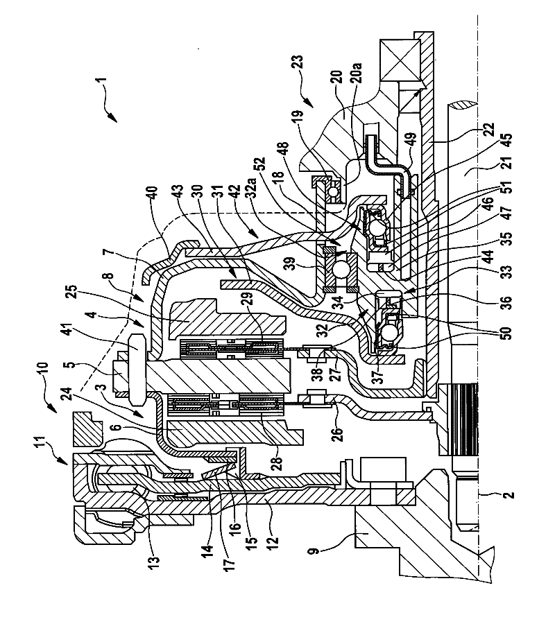
[0037] figure 1 A partial section of the dual clutch 1 above its axis of rotation 2 is shown. The dual clutch 1 comprises two friction clutches 3 , 4 which have a common central pressure plate 5 which is firmly connected to the housing parts 6 , 7 of the clutch housing 8 . The clutch housing 8 is driven by a crankshaft 9 of a not shown internal combustion engine. To this end, in the exemplary embodiment shown, a torsional vibration damper 10 , here in the form of a dual-mass flywheel 11 , is connected to the input part 12 of the crankshaft 9 . The output part 14 , which can be twisted to a limited extent relative to the input part 12 against the action of the energy store 13 , has an axially protruding profiled toothing 15 into which a complementary profiled toothing 16 engages, such as the housing shown Internal toothing of part 6. In this case, the dual clutch 1 is relative to the crankshaft 9 and relative to the torsional vibration damper 10 by means of an axially actin...


PUM


Abstract

The invention relates to a dual clutch (1) having two friction clutches (3,4), having a central pressure-exerting plate (5) and having two pressure plates (24,25) which are axially movable relative to said pressure-exerting plate (5) with the interposition of the friction linings (28,29) of two clutch disks (26,27), which mesh with in each case one gearbox input shaft, of actuating devices. Here, the pressure plates (24,25) are advantageously acted on by transmission elements (30,42) by the actuating devices (32,32a) directly without a lever action. Furthermore, for the cooling and lubrication of the actuating bearings (37,45) between the actuating devices (32,32a) and the transmission elements (30,42), an annular chamber (153) can be formed which has an increased fluid volume.

Description

technical field [0001] The invention relates to a double clutch with two friction clutches driven by a drive unit, the friction clutches having a common clutch housing and a pressure plate fixedly connected to the friction clutch housing and having two pressure surfaces and two axially deflectable pressing plates each facing a pressing surface. Background technique [0002] Double clutches with two friction clutches are known, which have a clutch housing and a central pressure plate fixedly connected to the housing. In this case, the actuating device axially deflects the pressure plate by axially acting on the disk spring or the lever element radially inwardly with a predetermined disengagement stroke. In this case, they are designed as one-armed or two-armed levers in the formation of the transmission ratio, depending on whether the corresponding friction clutch is configured as positively engaged, that is, forcibly closed or as pressed, that is, forcibly opened. Supporte...

Claims


Application Information

Patent Timeline
IPC IPC(8): F16C33/76F16D25/12F16D21/06F16D25/08
CPCF16C33/761F16D21/06F16D25/083F16C33/58F16D2021/0669F16D25/123F16D25/087F16C2361/43F16C37/00F16C19/54F16D2021/0692F16D25/10F16D2021/0607
Inventor O·诺尔I·阿格纳N·拉丁格
Owner SCHAEFFLER TECH AG & CO KG
Why Eureka
Try Eureka