Sectional dynamic machine-oil pressure fault inspecting system of engine

An engine oil, dynamic detection technology, used in engine testing, engine components, machines/engines, etc., can solve problems such as undetectable and low oil pressure

Active Publication Date: 2006-11-01
上海新动力汽车科技股份有限公司
View PDF0 Cites 5 Cited by
  • Summary
  • Abstract
  • Description
  • Claims
  • Application Information

AI Technical Summary

Problems solved by technology

However, this detection method under static conditions cannot detect the failure of low oil pressure due

Method used


Image

  • Sectional dynamic machine-oil pressure fault inspecting system of engine

Examples


Embodiment Construction

[0007] Preferred modes of the present invention are given by the following drawings.

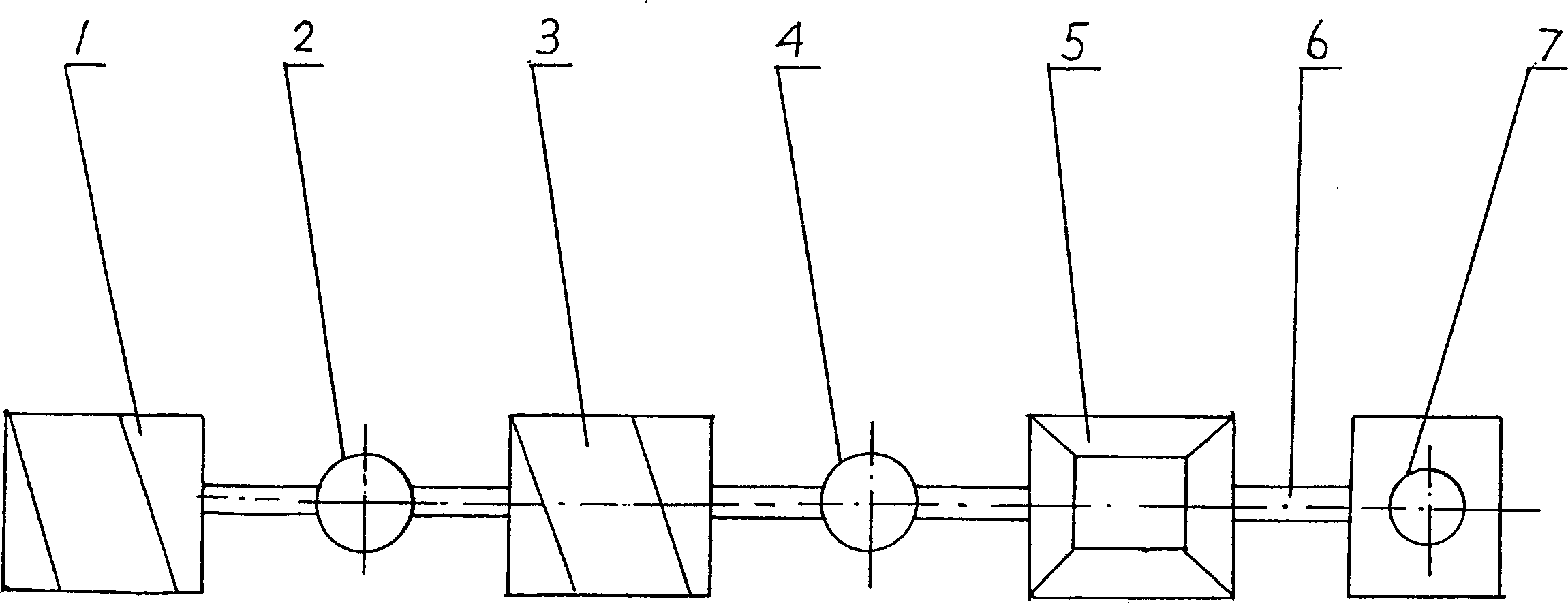
[0008] see figure 1 , engine oil pressure failure segmentation dynamic detection system, engine lubrication system consists of oil pump (1), oil cooling filter (3), main oil passage (5), oil pipeline (6) and terminal pressure monitoring gauge (7 ) composition, between the outlet of the oil pump (1) and the inlet of the oil cooling filter (3) and between the outlet of the oil cooling filter (3) and the inlet of the main oil passage of the engine (5), take the removal of the lubrication system In the method of the middle bulkhead, a disc-shaped first intermediate pressure gauge (2) and a disc-shaped second intermediate pressure gauge (4) are respectively installed in series at the original position where the bulkhead is installed. The measuring ranges of the two intermediate pressure gauges are both (0~10) Kg / cm 2 . When the engine is placed on the test bench and is in running state, by com...


PUM


Abstract

The invention relates to a section dynamic testing system for the engine oil pressure fault, in which in the engine lubricating system consisting of an engine oil pump, an engine oil cooling filter, a main oil channel, an engine oil pipeline and an end pressure monitoring meter a first central pressure gage is mounted in series between the outlet of the engine pump and the inlet of the engine oil cooling filter and between the outlet of the engine oil cooling filter and the inlet of the main oil channel is mounted in series a second central pressure gage. In a running state of the engine, the changes of the three node pressure values are measured sectionally by the central pressure gages.

Description

1. Technical field [0001] The invention relates to a detection method for an engine oil pressure failure. 2. Background technology [0002] Since the engine lubrication system is responsible for the lubrication of moving parts, in order to ensure the normal operation of the engine, it is necessary to ensure a certain design pressure of the lubricating oil (oil) of the lubrication system. If the lubricating oil (engine oil) leaks, it will cause the pressure of the engine oil to drop, the engine will not work normally, and even cause serious consequences of seizing or damage to moving parts. For this reason, before leaving the factory, each engine must undergo a strict bench test to check whether the oil pressure is normal. If there is a problem with low oil pressure, it cannot leave the factory. It is necessary to find out the cause of the low oil pressure in time. , and take exclusionary measures. At present, maintenance personnel usually seal the lubricating oil passage w...

Claims


Application Information

Patent Timeline
IPC IPC(8): F01N1/20G01M15/00
Inventor 张惠琪
Owner 上海新动力汽车科技股份有限公司
Why Eureka
Try Eureka