Coil forming apparatus and method

a coil and coil technology, applied in the field of coil forming apparatus and method, can solve the problems of tangles and breaks, increase the free-fall distance of the coil, and disturb the controlled distribution

Inactive Publication Date: 2000-06-13
MORGAN CONSTR CO
View PDF11 Cites 15 Cited by
  • Summary
  • Abstract
  • Description
  • Claims
  • Application Information

AI Technical Summary

Problems solved by technology

This abrupt drop temporarily increases the free-fall distance of the rings, which in turn disturbs the controlled distribution being effected by the ring distributor rotating about the nose cone.
Ring overlapping is a major cause of tangles and breaks during subsequent rod payoff.

Method used


Image

  • Coil forming apparatus and method
  • Coil forming apparatus and method
  • Coil forming apparatus and method

Examples


Embodiment Construction

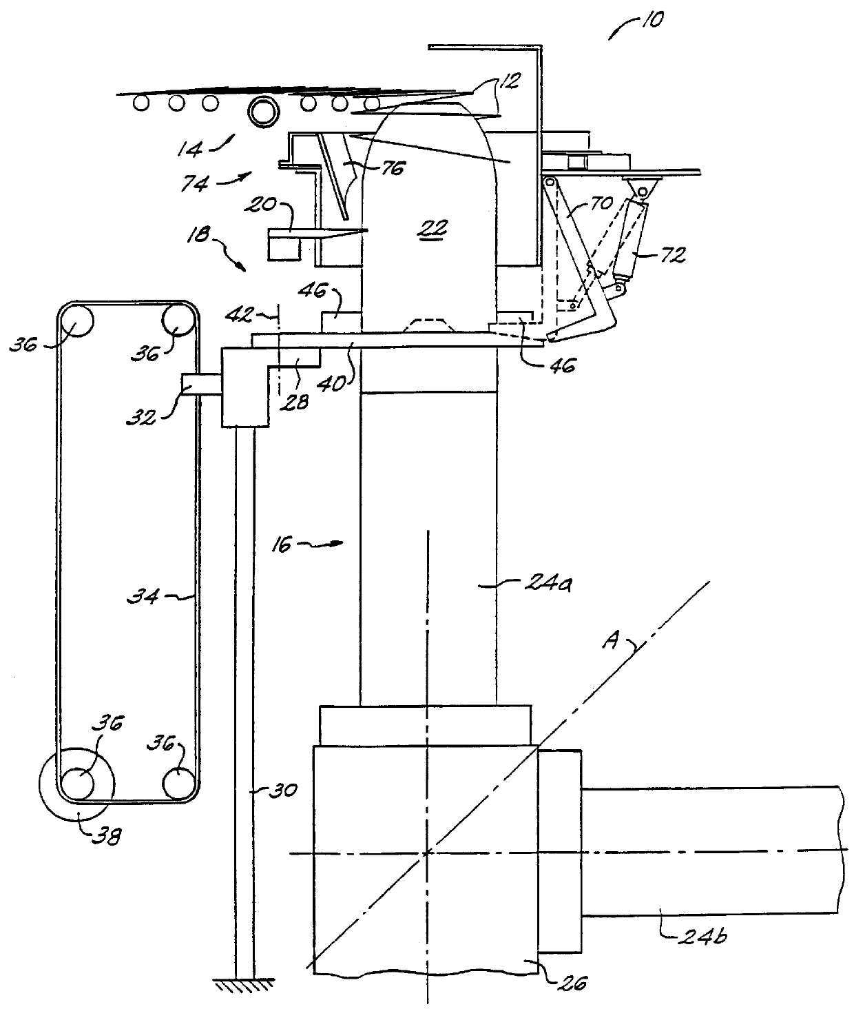
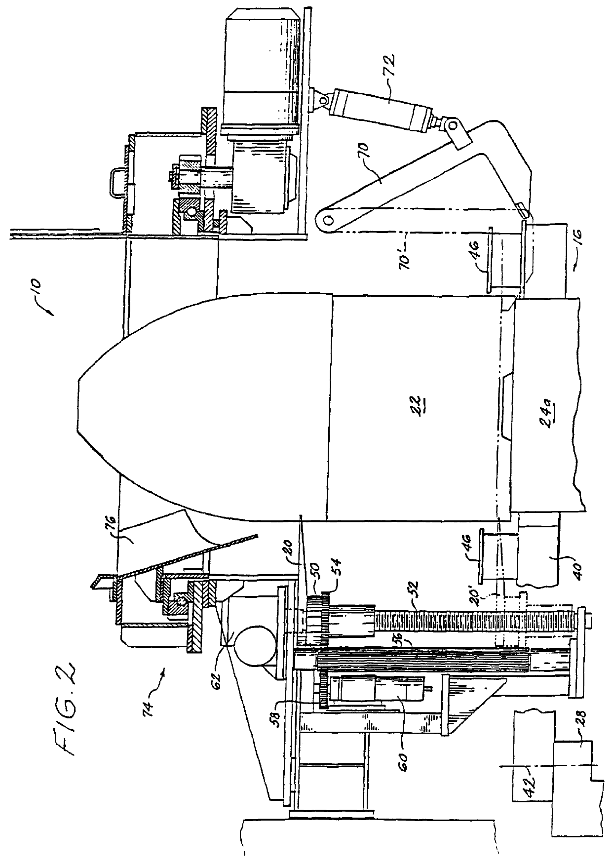
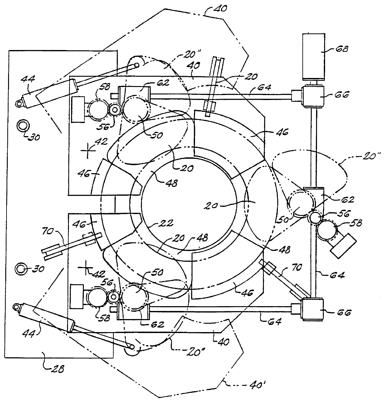
With reference initially to FIGS. 1-3, a reforming chamber in accordance with the present invention is shown at 10. The reforming chamber is positioned to receive a helical formation of rod rings 12 free falling from the delivery end of a conveyor 14.

The reforming chamber includes a vertically disposed guide generally indicated at 16, a vertically adjustable coil plate assembly 18, and vertically adjustable interceptor elements 20. The guide 16 is subdivided into an upper nose cone 22 positioned for encirclement by the helical formation of free falling rings 12, and one of two underlying mandrels 24a, 24b. The mandrels are carried on a base 26 which is rotatable about an axis A disposed at a 45.degree. angle with respect to the mandrel axes. Each mandrel is axially adjustable with respect to the base 26 by conventional means (not shown). At the operational stage shown in FIG. 1, the nose cone 22 is supported on the mandrel 24a.

The coil plate assembly 18 includes an elevator 28 movea...


PUM

PropertyMeasurementUnit
angleaaaaaaaaaa
heightaaaaaaaaaa
densityaaaaaaaaaa

Abstract

A method and apparatus is disclosed for receiving a helical formation of rings free falling from the delivery end of a conveyor and for gathering the rings into an upstanding cylindrical coil, The free falling rings encircle a vertically disposed guide and are supported initially on elevated intercepting elements. The interceptor elements are gradually lowered past a coil plate onto which the accumulated rings are transferred. The coil plate is then lowered to accommodate continued formation of the coil, and the intercepting elements are returned to their elevated position.

Description

1. Field of the InventionThis invention relates generally to rod rolling mills where hot rolled steel rod is formed into a continuous series of rings, and the rings are deposited in an overlapping pattern on a conveyor on which they are subjected to controlled cooling. The invention is concerned in particular with an improvement in the reforming chambers employed to receive and gather the rings into coils as they free fall from the delivery ends of the cooling conveyors.2. Description of the Prior ArtIn the conventional reforming chambers, the rings free fall in a helical formation into a cylindrical enclosure. The rings alight on a coil plate where they accumulate in coil form around a central guide. The coil plate is lowered to compensate for the growing height of the coil.The central guide includes an upper nose cone which is separable from and carried on an underlying mandrel. A ring distributor rotates continuously around the nose cone to distribute the free falling rings in a ...

Claims


Application Information

Patent Timeline
Patent Type & Authority Patents(United States)
IPC IPC(8): B21C47/02B21C47/24B21C47/14B21B39/00B21B41/00B21C47/26B21D53/16B21D53/18B21D53/20
CPCB21C47/245B21C47/146B21C47/262B21C47/34
Inventor SHORE, T. MICHAELPUCHOVSKY, MELICHERSTARVASKI, RAYMOND R.
Owner MORGAN CONSTR CO
Why Eureka
Try Eureka