Floor-wiring structure and floor members for storing cable in such structure

a floor wiring and cable technology, applied in the direction of false floors, constructions, building components, etc., can solve the problems of reducing the quality of the cable-end conditioning on the working site, affecting the efficiency of office innovation, and requiring a considerable amount of time for these operations

Inactive Publication Date: 2000-06-20
SUMITOMO WIRING SYST LTD
View PDF9 Cites 62 Cited by
  • Summary
  • Abstract
  • Description
  • Claims
  • Application Information

AI Technical Summary

Benefits of technology

Thus, since the surplus of the wiring material is stored in the floor members for storing cable and maintained therein, cutt...

Problems solved by technology

Recently, in order to rationalize office organization, office innovation has become a very current issue.
Accordingly, a considerable amount of time is needed for these operations and for controlling the quality of the work thereafter.
Such difficulties tend to lower the quality of the cable-end conditioning on the working site.
Further, in the above operation, the cable is cut after being wired, so that there may not be eno...

Method used


Image

  • Floor-wiring structure and floor members for storing cable in such structure
  • Floor-wiring structure and floor members for storing cable in such structure
  • Floor-wiring structure and floor members for storing cable in such structure

Examples


Embodiment Construction

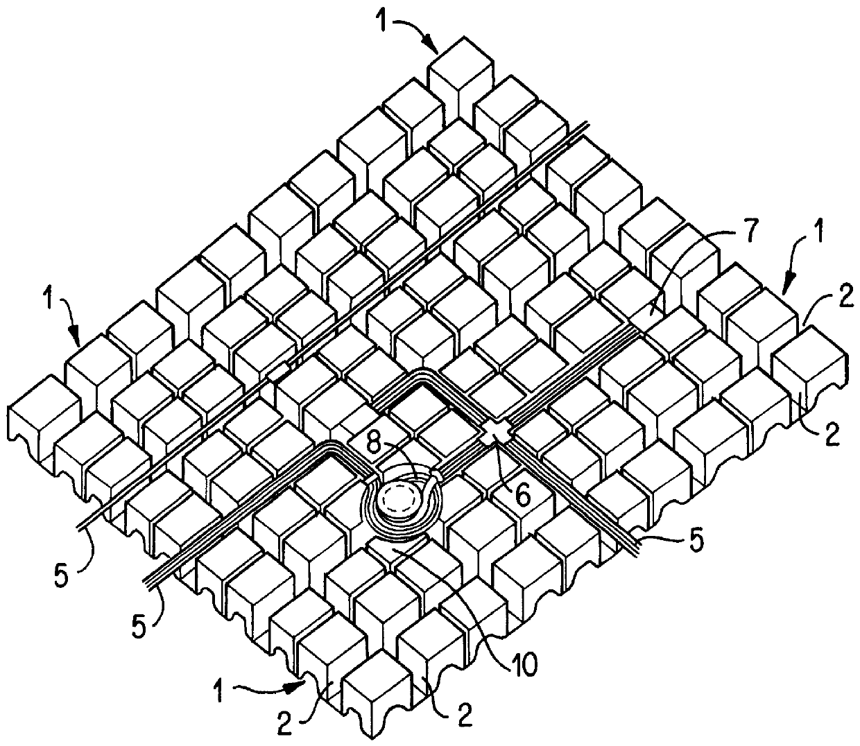
In FIG. 1, reference 1 indicates a unitary floor member. A plurality of unitary floor members are tiled or arranged preferably in a checkered pattern on the surface of a base floor to form a two-level floor structure.

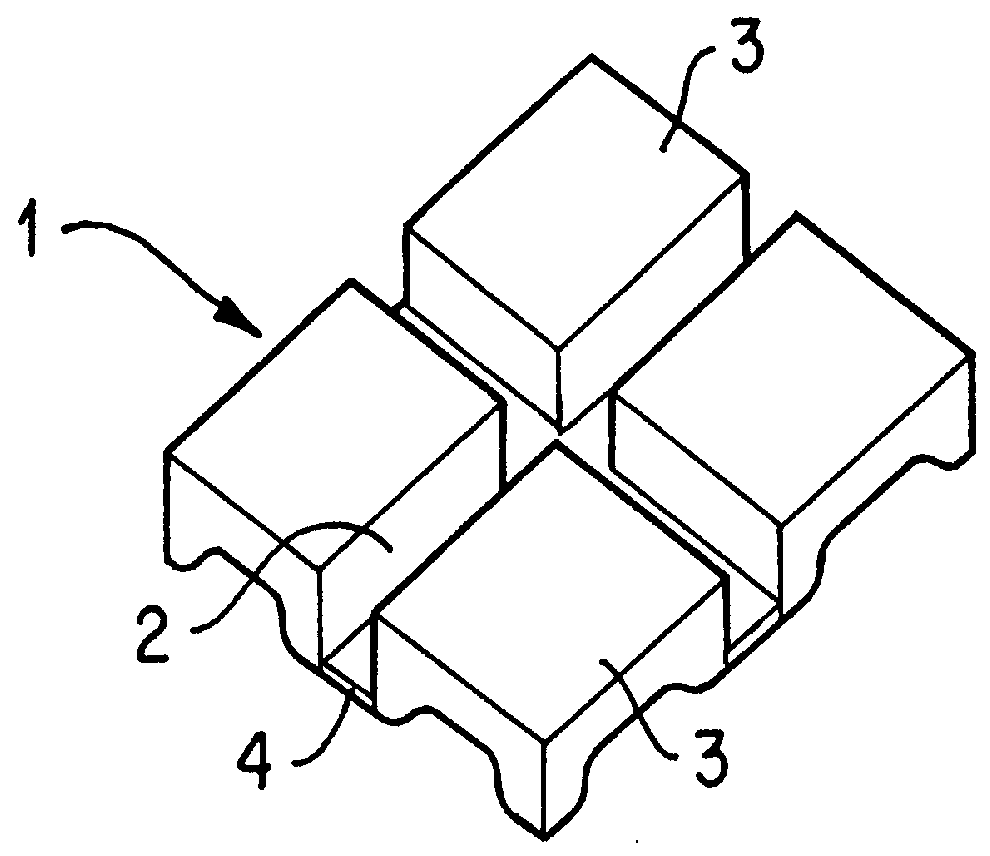
The above-mentioned unitary floor member 1 has a channel portion 2 which forms a path. In the above embodiment, as also shown in FIG. 2, there are integrally provided a plurality, preferably, four blocks 3 and a channel bottom portion 4. The side walls of the four blocks 3 face one another over channel portion 2. The channel bottom portion 4 constitutes the bottom of the channel portions defined by each pair of blocks 3. This configuration forms a unitary floor member 1 having a crossing channel portion 2. When a number of unitary floor members 1 are arranged in a checkered pattern, path-forming channel portions 2 of each unitary floor member 1 are connected linearly and perpendicularly thereto, for example in a grid-like pattern, thereby forming crosswise wiring pathwa...


PUM


Abstract

In the floor-wiring structure for wiring a cable, a space is secured for storing a surplus part of the cable. Cable-cutting work and end portion conditioning on the working site are thus dispensed with and the surplus part of the cable is easily stored. The structure comprises unitary floor members having a pathway channel. Some of the unitary floor members are replaced by a floor member for storing part of the cable. The latter floor member comprises an upwardly opened space for storing part of the cable, entrance-and-exit ports thereto or therefrom, a guide provided in the space for storing cable for maintaining the cable in a looped state and a cable-fixing band provided in the same space for fixing the cable in a freely removable way.

Description

1. Field of the InventionThe present invention relates to a floor-wiring structure applied to the floor parts in a construction or building and to a member for floor wiring used in this structure.2. Description of Related ArtRecently, in order to rationalize office organization, office innovation has become a very current issue. It includes, for example, replacement or installation of office automation (OA) apparatus, lay-out modification due to office reorganization, etc. In accordance with this tendency, an increasing number of wiring systems have been developed. A prevailing system is a floor-wiring structure.As a floor-wiring structure, there already exists a double-floor structure in which unitary floor members are tiled or arranged side-by-side and head-to-tail (in a checkered pattern) on a base floor. This type of structure is disclosed, for example, in Japanese Patent Application published before examination under the No. 8-130821.Usually, after installing those unitary floo...

Claims


Application Information

Patent Timeline
IPC IPC(8): E04F15/024E04C2/52H02G3/36H02G3/38H02G3/00H02G3/18
CPCH02G3/285A47B2097/003
Inventor KONDO, NAOHIRO
Owner SUMITOMO WIRING SYST LTD
Why Eureka
Try Eureka