Rolling mill, hot rolling system, rolling method and rolling mill revamping method

a hot rolling system and rolling mill technology, applied in the field of rolling mills, can solve the problems of increasing the overall size of the rolling mill, reducing productivity, and complicated structure of the rolling mill

Inactive Publication Date: 2000-06-20
HITACHI LTD
View PDF49 Cites 11 Cited by
  • Summary
  • Abstract
  • Description
  • Claims
  • Application Information

AI Technical Summary

Benefits of technology

A second object of the present invention is to provide a work roll crossing type rolling mill, which has an excellent capability with which it controls crown of materials to be rolled, which achieves reduction in the thrust exerted to the work rolls by a simple structure, and which allows for schedule free rolling.
In the tenth aspect of the present invention, hydraulic devices are provided on a position on the rolling stand which opposes a roll chock of the work roll in such a manner that they can be operated in a direction in which a material being rolled proceeds, so that they can incline axes of the work rolls relative to the back-up rolls on a horizontal plane such that the axes of the work rolls cross axes of the back-up rolls and such that the axes of the work rolls cross each other. A hydraulic device is provided on the rolling stand in such a manner that it can be operated in an axial direction of the work roll, so that it can engage with the roll chock of the work roll and thereby move the work roll in the axial direction thereof. A lubricant supply device for supplying a lubricant between the work roll and the back-up roll is provided. It is therefore possible to provide a rolling mill in which crossing of only the work rolls is realized utilizing an existing rolling mill stand. Furthermore, since the work rolls can be moved in the axial direction during rolling, schedule free rolling is allowed. Furthermore, the thrust exerted to the work roll can be reduced to a degree at which it causes no problem in a practical operation even when the work rolls cross each other by the action of the lubricant supplied between the work roll and the back-up roll. Therefore, revamping of a rolling mill, which shows an excellent ability with which it controls cross of the materials to be rolled and in which the work rolls cross each other, is made possible.

Problems solved by technology

However, provision of such a rigid beam increases the overall size of the rolling mill.
This makes the structure of the rolling mill more complicated.
Also, a troublesome maintenance is necessary due to scales entering the lower portion of the rolling mill stand, and productivity is greatly reduced.
The rolling mill in which crossing of only the work rolls is performed cannot be put into practical use for the following two reasons.
However, it is very difficult for the work roll whose diameter is one half or less than that of the back-up roll to do that.
The second reason is roll wear caused by relative slip between the back-up roll and the work roll.
However, changing of the back-up roll takes place every 10 or 20 days and requires a long time.
Therefore, frequent changing of the back-up rolls due to rapid wear greatly reduces productivity.
However, in the work roll crossing type mill used as the hot rolling mill, a lubricant has not been used because a large amount of high-pressure water (coolant) supplied to cool the surface of the roll may wash away a lubricant, reducing the lubricating effect to zero (or to a very small level), or because the lubricant which reaches the material being rolled located between the work rolls (a roll bite portion) may prohibit bite of a subsequent material to be rolled.

Method used


Image

  • Rolling mill, hot rolling system, rolling method and rolling mill revamping method
  • Rolling mill, hot rolling system, rolling method and rolling mill revamping method
  • Rolling mill, hot rolling system, rolling method and rolling mill revamping method

Examples


Embodiment Construction

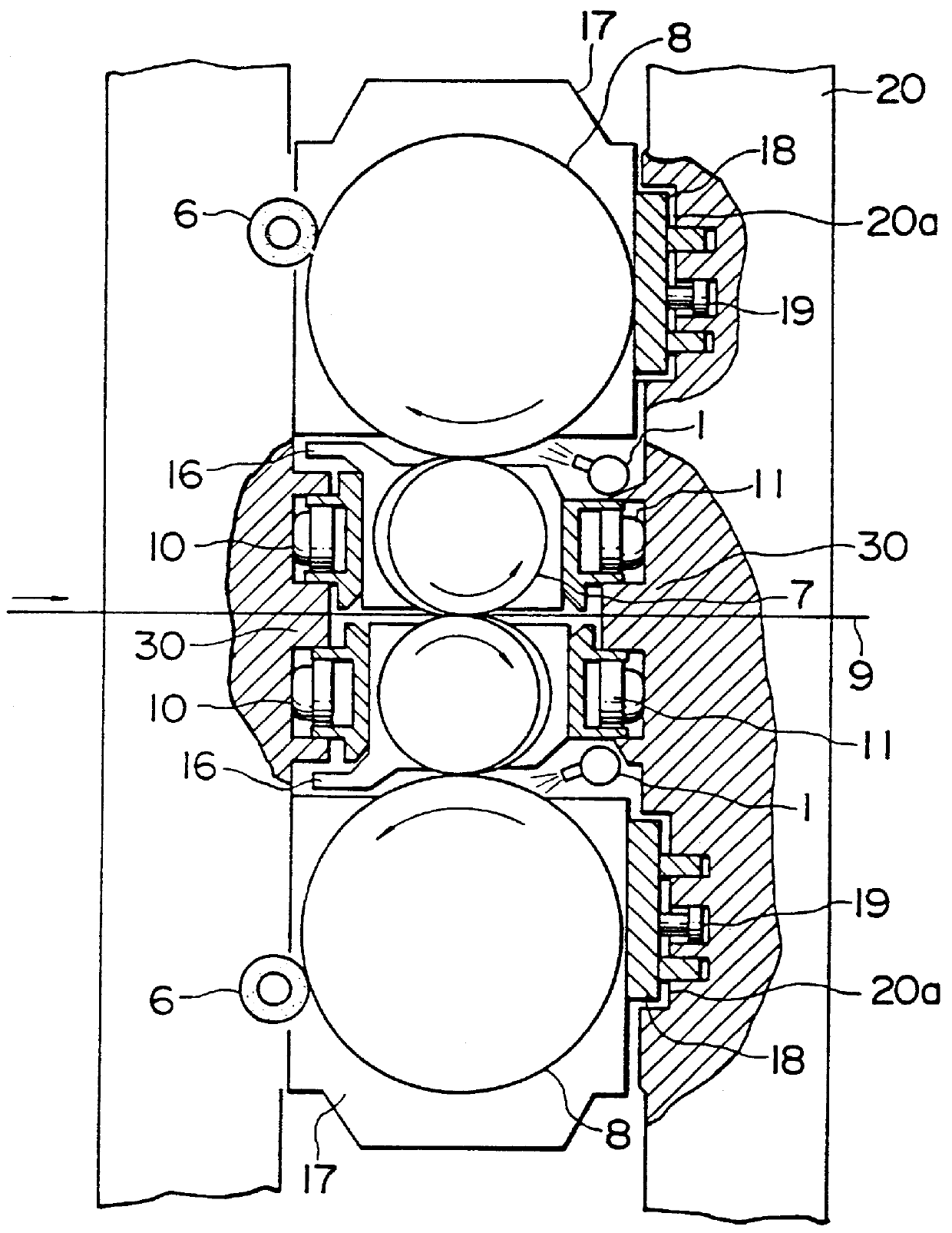
Referring to FIGS. 1 and 2, a cross type four high rolling mill includes upper and lower work rolls 7 and upper and lower back-up rolls 8 which support the work rolls. Work roll chocks 16 are provided at the roll ends of each of the work rolls 7 so as to rotatably support the work roll 7. Similarly, back-up roll chocks 17 are provided at the roll ends of each of the back-up rolls 8 to rotatably support the back-up roll 8.

The work roll chocks 16 and the back-up rolls chocks 17 are disposed such that they oppose window surfaces 20a of a pair of stands 20 provided erect in spaced relation in the roll axial direction of the rolling mill. Rolling loads are exerted to the individual rolls by means of jacks (not shown) provided in an upper or lower portion of the stands 20 to roll a material to be rolled 9.

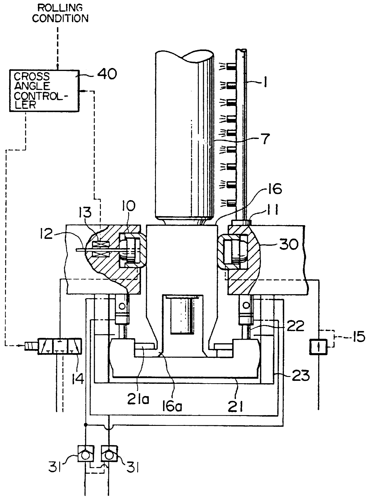
To make the axes of the upper and lower work rolls 7 inclined relative to the axes of the back-up rolls 8 on a horizontal plane and to make the axes of the upper and lower work rolls 7 c...


PUM

PropertyMeasurementUnit
timeaaaaaaaaaa
timeaaaaaaaaaa
cross angleaaaaaaaaaa

Abstract

A work roll crossing type rolling mill has back-up rolls arranged in such a manner that their axes are not inclined in a horizontal plane. Work rolls are constructed in such a manner that their axes can be inclined in a horizontal plane relative to the backup rolls such that the axes of the work rolls cross the axes of the back-up rolls and such that the axes of the work rolls cross each other. A lubricant supply device is provided for supplying a lubricant between each work roll and each back-up roll combination to greatly reduce the thrust exerted to the work rolls, whereby the rolling mill is given an excellent ability of controlling the crown of the material to be rolled.

Description

1. Field of the InventionThe present invention relates to a rolling mill and, more particularly, a work roll crossing type sheet rolling mill which exhibits an excellent ability with which it controls the crown of materials to be rolled, as well as a hot rolling system, a rolling method and a rolling mill revamping method.2. Description of the Prior ArtIn roll cross type four high rolling mills which are available on the market, a roll pair consisting of an upper work roll and an upper back-up roll and a roll pair consisting of a lower work roll and a lower back-up roll are moved such that the axes of the two roll pairs cross each other on a horizontal plane. Such roll cross type four high rolling mills have been described in, for example, Mitsubishi Heavy Industrial Co., Ltd. Technical Report, Vol. 21, No. 6 (1984) from p61 to p67.Four high rolling mills in which crossing of only the work rolls is performed have been proposed earlier than the pair cross type rolling mills in, for e...

Claims


Application Information

Patent Timeline
Patent Type & Authority Patents(United States)
IPC IPC(8): B21B27/06B21B27/10B21B28/00B21B37/28B21B28/04B21B13/00B21B13/02B21B31/16B21B37/00B21B31/18B21B15/00B21B1/26B21B31/07B21B35/12
CPCB21B13/023B21B27/10B21B28/04B21B37/28B21B1/26B21B15/0085B21B2265/12B21B31/185B21B35/12B21B37/007B21B31/07
Inventor KAJIWARA, TOSHIYUKISUGIYAMA, TOKUJITAKAKURA, YOSHIOSAKANAKA, TAKAOYOSHIMURA, YASUTSUGUYASUDA, KEN-ICHIKAGA, SHINICHI
Owner HITACHI LTD
Why Eureka
Try Eureka