Control process for continuous skin pass operation for metal strip

a control process and skin pass technology, applied in the direction of tension/compression control device, roll mill control device, manufacturing tools, etc., can solve the problems of insufficient precision and too long response tim

Inactive Publication Date: 2000-06-27
SOLLAC (SA)
View PDF8 Cites 29 Cited by
  • Summary
  • Abstract
  • Description
  • Claims
  • Application Information

AI Technical Summary

Benefits of technology

It is an object of the present invention to eliminate the above disadvantages.

Problems solved by technology

This type of control process for skin-pass mills has numerous disadvantages for adjustment of the strip extension rate (adjustment B), including, among others, a response time that is too long, for it must remain longer than that of adjustment A; insufficient precision, more particularly due to the dead strip and the complexity (non linear) of the transfer function.

Method used


Image

  • Control process for continuous skin pass operation for metal strip
  • Control process for continuous skin pass operation for metal strip
  • Control process for continuous skin pass operation for metal strip

Examples


Embodiment Construction

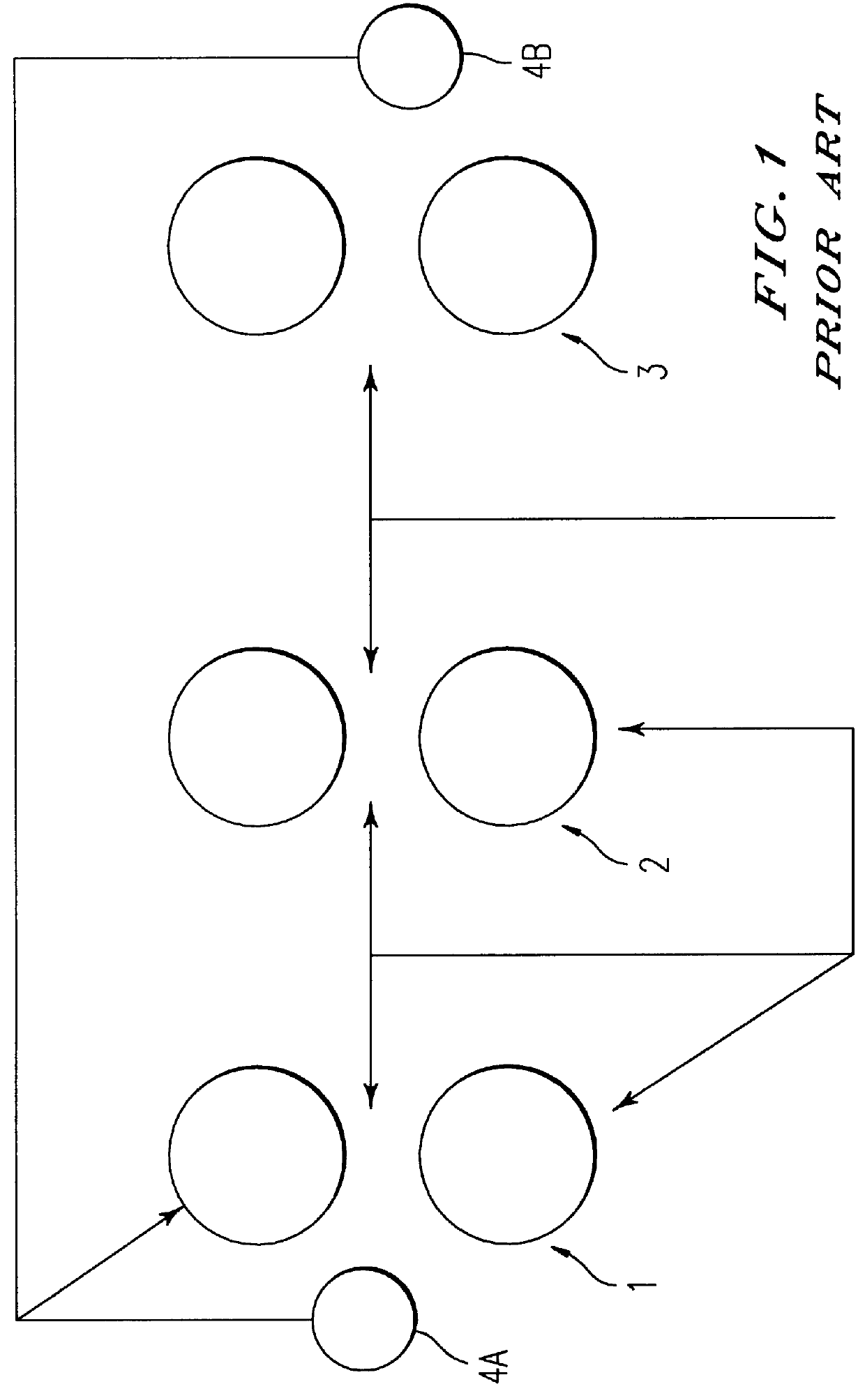
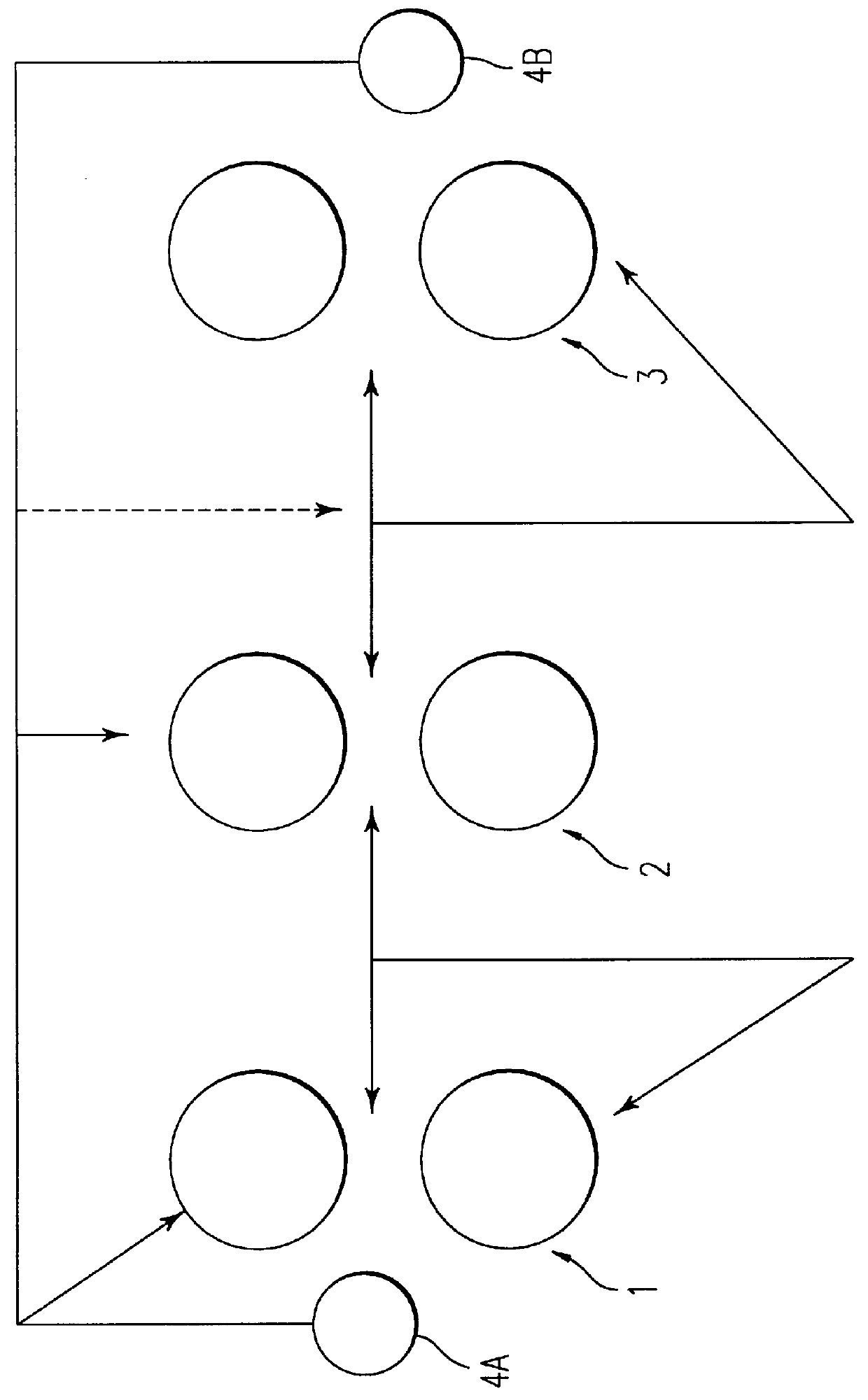
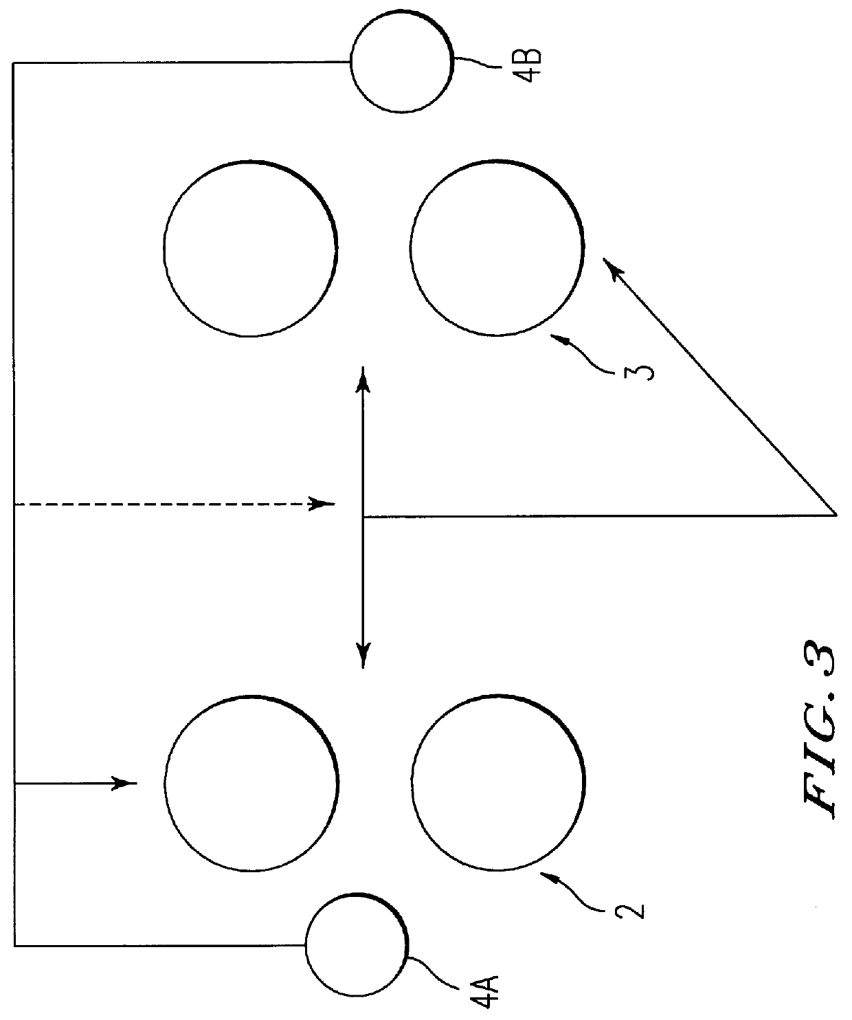
In FIGS. 1 to 3 and 5 to 7, by convention, the strip travels from left to right (see arrow in FIG. 5). Referring to FIG. 5, the continuous skin-pass mill for metal strip comprises, in the direction of travel of the strip B, an unwinder (7), an entry S-block (1'), a first press stand (2), a second press stand (3), an exit S-block (1') and a rewinding stand (6).

The unwinder (7) and the rewinding stand (6) are standard types and will not be described in detail.

The "S-blocks" (1', 5) are each composed of two strip bearing rollers, and serve in a standard fashion to vary the tension of the strip B. One of the rollers of each block is equipped with speed indicator devices (4A, 4B) providing precision measurement of the speed of passage of the strip B through the blocks (1', 5).

Each press stand (2, 3) comprises two working rollers, each supported by a bearing cylinder. Devices that are not shown allow one to vary the squeezing force of the working rollers against each other. Other devices ...


PUM

PropertyMeasurementUnit
response timeaaaaaaaaaa
thicknessaaaaaaaaaa
tensionaaaaaaaaaa

Abstract

A method of controlling a continuous skin-pass and reduction operation for a metal strip includes the steps of passing a strip through a gap between working rollers of at least two successive rolling stands, only an upstream one of the stands providing substantial thickness reduction of the strip; determining an extension rate of the strip provided by the upstream stand; determining a tension of the strip downstream of the upstream stand; adjusting the speed of the working rollers of the upstream stand compared to the speed of the working rollers of a downstream one of said stands according to the determination of the extension rate; and adjusting the squeezing force of the upstream stand according to the downstream tension determination. A response time to the step of adjustment of the squeezing force is longer than a response time to the step of adjusting the speed of the working rollers.

Description

1. Field of the InventionThe invention concerns a control process for a continuous skin pass and reduction operation for a metal strip in a skin pass mill comprising at least two successive roll stands.2. Description of the Related ArtBy skin pass and reduction operation is meant an operation conventionally called a "skin pass" or a second reduction rolling operation (called "DR"). For this type of operation one generally uses roll mills comprising at least two successive stands, of which only one, called the reduction stand, accomplishes the essential portion of the thickness reduction of the strip. In the case of a roll mill consisting of two stands, the reduction stand is the upstream stand or first stand, and in a roll mill consisting of three stands, the reduction stand is the second stand; the one in the middle of the installation.A roll or skin-pass stand of this type of mill comprises two working rollers rotating in opposite directions, in the gap of which a metal strip can ...

Claims


Application Information

Patent Timeline
Patent Type & Authority Patents(United States)
IPC IPC(8): B21B37/56B21B1/22
CPCB21B37/56B21B2001/228
Inventor ALLEGRO, FERNANDBERTOLINI, FREDERICDEVOS, RODOLPHEMIEZE, REGISREYNOUDT, PHILIPPESPARTY, BRUNOCHAUVIRE, MICHELREVOIR, GILLESBECLER, DIDIERSILVY-LELIGOIS, CHRISTOPHE
Owner SOLLAC (SA)
Why Eureka
Try Eureka