Plastic bag rack

a plastic bag rack and rack technology, applied in the field of plastic bag racks, can solve the problems of waste of materials, no longer supporting the sides, and the plastic bag rack still does little more to improve the actual packing of the bag,

Inactive Publication Date: 2000-07-11
HANDLE HELPER
View PDF11 Cites 33 Cited by
  • Summary
  • Abstract
  • Description
  • Claims
  • Application Information

AI Technical Summary

Benefits of technology

Briefly described, the bag rack of the present invention includes a base, a back wall extending upwardly from the base, left and right side walls, each extending between the back wall and the base, and a pair of spaced-apart bag support arms for releasably joining the side walls to the back wall. Each bag support arm includes an upper section extending above the base, cantilevered outwardly over the base, in position for support of a T-shirt bag in a distended condition over the base for filling of the bag. The side walls provide structural support to the back wall in order to maintain the bag support arms in position above the base as a bag is filled with items.
According to an aspect of the invention, the side walls and back wall can be repositioned relative to the base in order to provide for efficient stacking of multiple bag racks. Preferably, the side walls and back wall can be positioned generally in the plane of the base in order to create a substantially flat configuration, which greatly simplifies packaging of multiple bag racks for shipment as well as the manufacturing process. The preferred design of the side walls includes a pivotal joint between the side walls and the base, such as a thin-wall line that creates a hinge-like connection.
According to an aspect of the present invention, the side walls, together with the back wall, define a structural template for baggers to easily and quickly position the first items packed in the bag around the interior perimeter of the bag, thereby increasing the speed with which a bagger can properly pack the bag. The side walls are formed in a manner that does not permit the placement of the perimeter items to exceed the internal dimensions of the bag, thereby preventing items pressed against one side of the bag from pulling over items placed on the opposite side of the bag and providing a surface against which the first taller items may lean upright.
According to another embodiment of the present invention, the perimeter of the base adjacent the side walls and back wall is formed with a slight downward slope from the center of the base. When a bag is held by the bag support arms in an open configuration for receipt of items, the downwardly sloping perimeter of the base tilts items placed around the interior perimeter of the bag outwardly, against the side walls and back wall. This holds the perimeter items in place and prevents them from falling over into the bag as subsequent items are placed into the center of the bag.
According to another embodiment of the present invention, the bag rack comprises a base having upwardly turned side edges and an upwardly turned rear edge, a back wall extending upwardly from the base, and a pair of spaced apart bag support arms mounted to the back wall above the base and having lengths cantilevered outwardly from the back wall over the base by a distance sufficient for support of T-shirt bags thereon in a distended condition for filling. The bag support arms have a relatively thin transverse cross section over substantially their entire lengths for sliding receipt of mounting apertures of T-shirt bags thereon to enable positioning and support of a plurality of T-shirt bags on the arms proximate the back wall. The back wall includes an opening adjacent the base for receiving the bottom edges of the plurality of T-shirt bags supported on the bag support arms. The slot allows the bags to be positioned out of the way so they do not interfere with the upwardly turned rear edge as a front bag is loaded.

Problems solved by technology

For all their advantages and speed in opening bags, however, plastic bag racks still do little more to improve actual packing of the bag than to suspend the bag in an open position.
When they are removed and placed on the counter or in a shopping cart, the sides are no longer supported and, as a result, they slump down as the groceries shift and lean against the thin sides of the bag that offer no support.
Lower item counts per bag lead to higher bagging costs and also waste material.
Such a proper packing procedure requires considerable care because the thin, flexible sides of the bag provide no support for the initial items around the bag's perimeter.
Packing with one hand not only slows the bagging process, repetitive leaning and reaching can introduce ergonomic hazards as well.
Again, plastic bag racks have made very little real progress in addressing the difficulty inherent in packing thin, flexible, difficult to control bags.
Such careful packing of the bags is seldom accomplished.
The situation is exacerbated by the youth and high rates of turnover among store employees hired to pack bags.
The demands placed on baggers to get customers through the checkout line result in poorly packed, and therefore under-filled bags.
Retailers complain about the under filling of plastic bags and the associated costs, and the plastic bag manufactures respond by generating training materials to counteract improper and under filled bags.
If these training efforts are begun at all, they are typically abandoned in short order due to the sheer volume of people who go through these positions.
The sheet metal racks were also awkward to unload as the loops of a full bag had to be unhooked from the pegs.
Another disadvantage of the sheet metal racks was their tall parallel sides.
When a bagger over-filled a bag, the bag would be difficult to remove due to the friction against the opposed side walls.
These wire racks, like their predecessors provided strength but required numerous secondary operations to construct.
The number of secondary manufacturing operations required to construct these racks have made them costly to produce.
Adding to their cost is the fact that they are cube-shaped with parallel sides which makes nesting impossible and can therefore only be shipped and stored two in a box.
Thus, cost is a paramount concern.
Yet another disadvantage of the current formed and welded wire racks is the proliferation of alternative plastic bag sizes in recent years.
The current bag racks suffer from other deficiencies as well.
Either way, once mounted, the racks are inevitably too low for some individuals and too high for others.

Method used


Image

  • Plastic bag rack
  • Plastic bag rack
  • Plastic bag rack

Examples


Embodiment Construction

Reference will now be made in detail to the preferred embodiments of the invention, examples of which are illustrated in the accompanying drawings. While the invention will be described in conjunction with the preferred embodiments, it will be understood that the described embodiments are not intended to limit the invention specifically to those embodiments. On the contrary, the invention is intended to cover alternatives, modifications and equivalents, which may be included within the spirit and scope of the invention as defined by the appended claims.

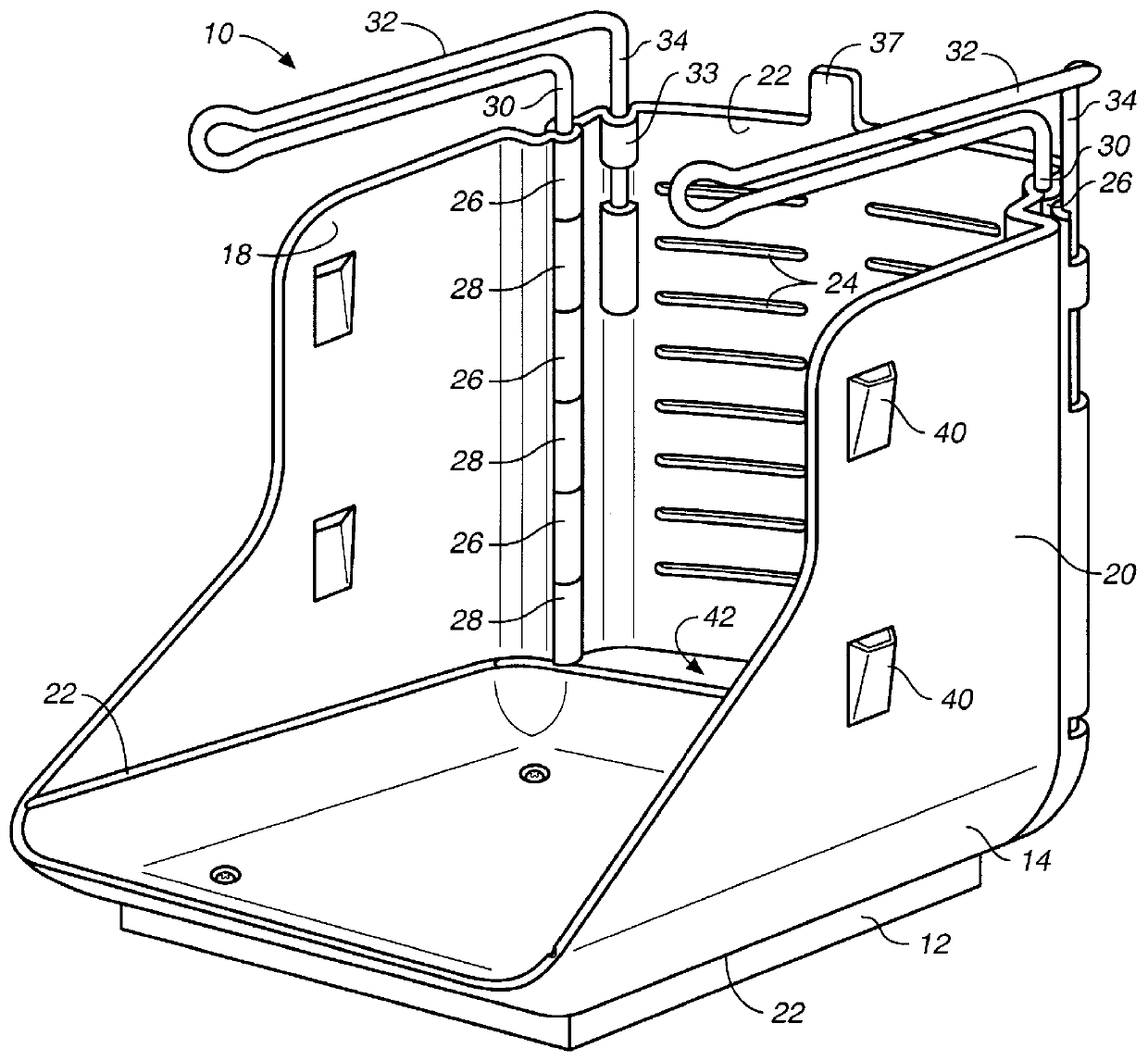
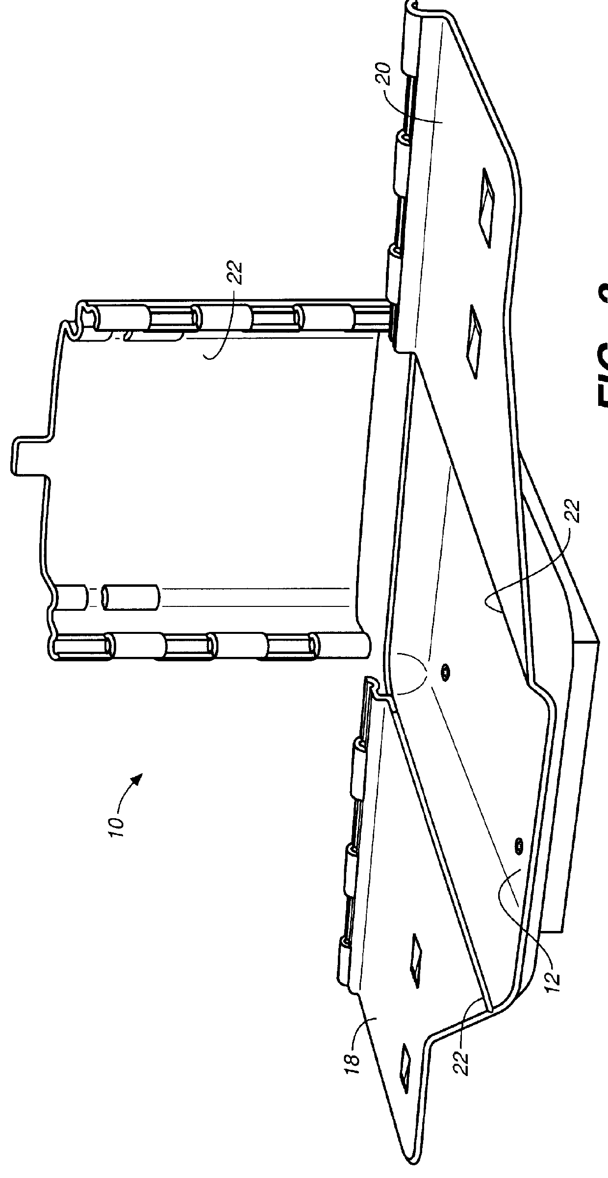
Referring to FIG. 1, the bag rack 10 of the present invention includes a rectangular base 12 having upwardly turned side edges 14, an upwardly turned back edge 16, and an upwardly turned front edge 17 that is formed lower than side edges 14.

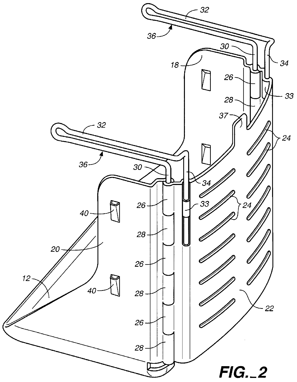
Bag rack 10 includes a pair of left and right side walls 18, 20 and a detachable back wall 22. Preferably, side walls 18, 20 are formed monolithically with base 12, with thin wall hinges 22 formed ...


PUM


Abstract

A bag rack (10) including a base (12), side walls (18, 20), a back wall (22) and a pair of L-shaped bag support arms (32). Side walls (18, 20) are releasably joined and secured to back wall (22) by the upright legs (30) of bag support arms (32) by means of a series of interlocking, aligned slots (26, 28). A rear slot (42) is provided between back wall (22) and base (12) to allow the bottom edges of a multiplicity of bags carried by a hook (37) to extend back of base (12).

Description

This invention relates to bag racks for dispensing and packing of plastic bags, particularly of the T-shirt type.Plastic T-shirt bags have largely displaced paper bags over the last twelve years in grocery and other major retail markets. One of the major reasons for the market success of plastic bags, aside from their inherent cost advantage, has been the development of racks to manage the thin, flexible and difficult to control bags. Unlike a paper bag that can stand up on its own while being loaded with groceries, plastic bags initially required a packer to hold the bag up in an open position with one hand and load the groceries with the other hand.The primary function of early plastic bag racks was to hold the bags suspended over a base in an open position, freeing the packer to use both hands to load the groceries. Following these early racks were numerous bag rack designs that improved the speed with which the bags could be opened, packed and removed. Bag racks were developed t...

Claims


Application Information

Patent Timeline
Patent Type & Authority Patents(United States)
IPC IPC(8): B65B67/00B65B67/12
CPCB65B67/1227E05Y2900/402
Inventor KERR, JONATHAN F.DIETERICH, JR., PETER D.FISCHER, ROY K.
Owner HANDLE HELPER
Why Eureka
Try Eureka