
Battery cell

a battery cell and battery technology, applied in the field of batteries, can solve the problems of battery cell damage, difficulty in efficiently stacking battery cells, etc., and achieve the effect of avoiding positional shift, avoiding battery damage, and easy damag

Pending Publication Date: 2021-11-25
HONDA MOTOR CO LTD
View PDF1 Cites 0 Cited by
  • Summary
  • Abstract
  • Description
  • Claims
  • Application Information

AI Technical Summary

Benefits of technology

The present invention addresses the problem of module formation from battery cells by efficiently stacking them without shifting of their positions. The invention achieves this by using an exterior body that is joined onto the side surface of an adjacent battery cell to fix their positional relationship and prevent damage due to positional shift. This is particularly useful for all-solid-state battery cells which are prone to damage. The invention also uses a single film for the exterior body, reducing joint portions and improving sealability. Overall, the invention avoids battery cell damage and ensures their safe and effective use.

Problems solved by technology

It has been difficult to efficiently stack the battery cells without shifting of the positions of the battery cells from each other upon module formation from the battery cells.
When the positional shift is caused upon stacking of the battery cells, an equal surface pressure (binding force) cannot be applied to the battery cells, and the battery cells might be damaged due to a partially-excessive load.

Method used


Image

  • Battery cell
  • Battery cell
  • Battery cell

Examples


Embodiment Construction

[0025]Hereinafter, one embodiment of the present invention will be described in detail with reference to the drawings.

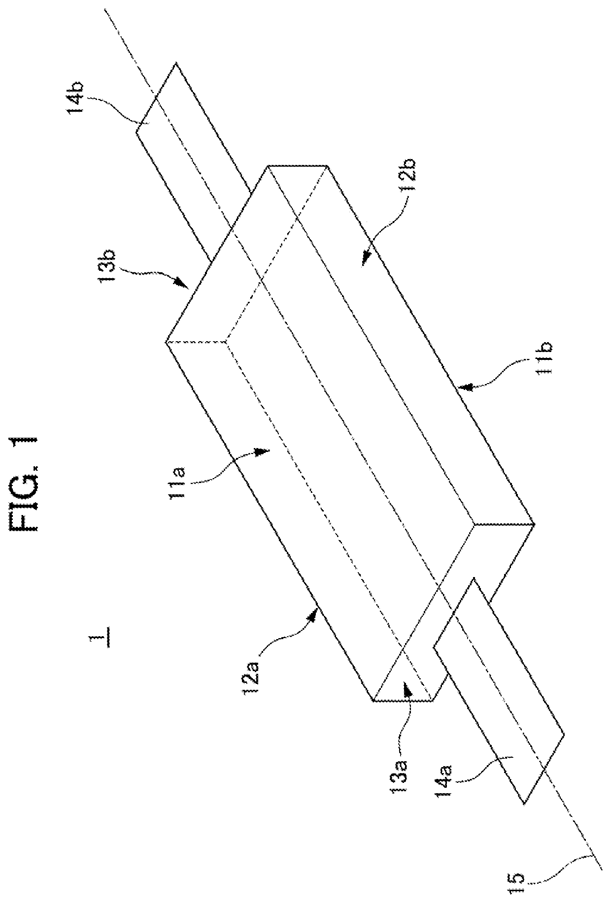
[0026]A battery 1 of the present invention is an all-solid-state battery in the embodiment, and is in a rectangular parallelepiped shape as shown in FIG. 1. The battery 1 has six surfaces including a top surface 11a, a bottom surface 11b, side surfaces 12a, 12b, and end surfaces 13a, 13b. Assuming a center axis 15 connects the centers of the end surfaces 13a, 13b to each other, each of collection tab leads 14a, 14b is provided to extend in the direction of the center axis 15 from a corresponding one of the end surfaces 13a, 13b. The all-solid-state battery is brittle and easily damaged particularly at a corner portion and a surface portion (an end surface portion), and for this reason, is more suitable for application of the configuration of each embodiment of the present invention.

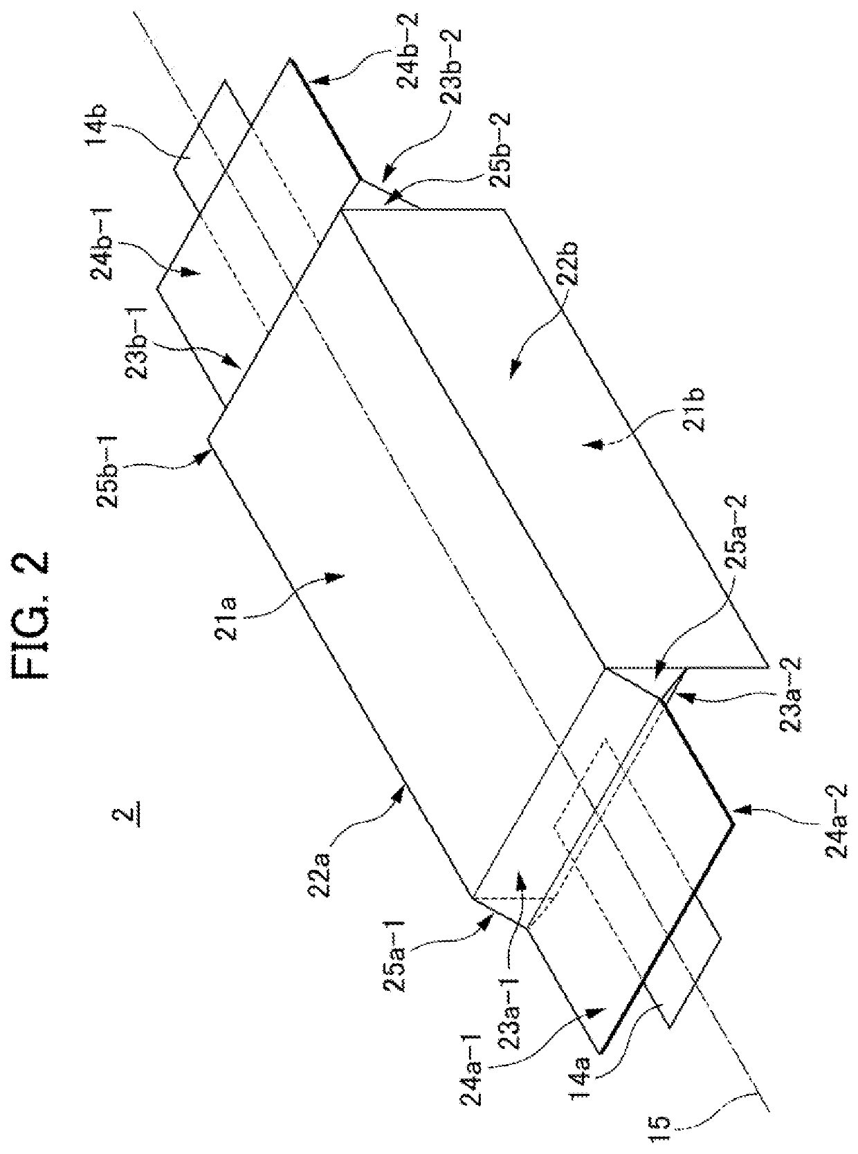
[0027]FIG. 2 shows a battery cell 2 configured such that the battery 1 of the present ...


PUM

PropertyMeasurementUnit
shape/dimensionaaaaaaaaaa
volume energy densityaaaaaaaaaa
surface pressureaaaaaaaaaa

Abstract

To efficiently stack battery cells without shifting of the positions of the battery cells from each other in view of the above-described problems on module formation from the battery cells.When the battery cells are stacked to form a module, the extension portion 22c of the exterior body of the battery cell 2 extending from the side surface of the battery on the side from which the collection tab lead does not extend is joined onto a side surface 22a, from which a collection tab lead does not extend, of an adjacent battery cell.

Description

[0001]This application is based on and claims the benefit of priority from Japanese Patent Application 2020-087101, filed on 19 May 2020, the content of which is incorporated herein by reference.BACKGROUND OF THE INVENTIONField of the Invention[0002]The present invention relates to a battery cell, and particularly relates to a battery cell sealed by an exterior body.Related Art[0003]In recent years, a demand for high-capacity high-output battery devices has rapidly grown due to popularization of various types of electric / electronic equipment with a variety of sizes, such as an automobile, a personal computer, and a mobile phone. Examples of these battery devices include a liquid battery cell using, as an electrolyte, an organic electrolytic solution between positive and negative electrodes and a solid-state battery cell using a fire-retardant solid electrolyte instead of using the organic electrolytic solution as the electrolyte.[0004]For these battery devices, a laminated cell type...

Claims


Application Information

Patent Timeline
Patent Type & Authority Applications(United States)
IPC IPC(8): H01M50/103H01M50/533H01M50/183H01M50/543
CPCH01M50/103H01M50/543H01M50/183H01M50/533H01M50/102H01M50/105Y02P70/50Y02E60/10H01M50/548H01M2300/0065H01M50/503H01M50/54
Inventor TANIUCHI, TAKUYAOHTA, MASAHIROARIGA, TOSHIYUKI
Owner HONDA MOTOR CO LTD
Learn More