Fluid dispensing utensil

a technology for utensils and fluids, applied in the direction of writing implements, printing, ink reservoir pens, etc., can solve problems such as unfavorable leakage, and achieve the effects of convenient manufacture, large volume of fluid, and low cos

Inactive Publication Date: 2000-07-18
DATAPRINT R KAUFMANN
View PDF29 Cites 85 Cited by
  • Summary
  • Abstract
  • Description
  • Claims
  • Application Information

AI Technical Summary

Benefits of technology

The general object of the present invention is to provide a fluid dispensing utensil which obviates, for practical purposes, the aforementioned problems in the art. In particular, one object of the present invention is to provide a fluid dispensing utensil which is capable of storing a relatively large volume of fluid without leaking during periods of container air expansion. Another object of the present invention is to provide a fluid dispensing utensil which is relatively inexpensive and easy to manufacture.

Problems solved by technology

This eventually results in undesired leakage.

Method used


Image

  • Fluid dispensing utensil
  • Fluid dispensing utensil
  • Fluid dispensing utensil

Examples


Embodiment Construction

The following is a detailed description of a number of preferred embodiments of the invention. This description is not to be taken in a limiting sense, but is made merely for the purpose of illustrating the general principles of the invention. The scope of the invention is defined solely by the appended claims.

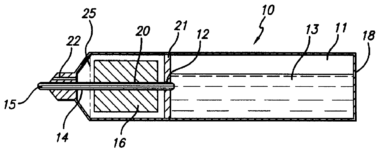
As shown by way of example in FIG. 1, a preferred embodiment of the present invention (generally represented by reference numeral 10) includes a housing 20 consisting of a container 11 for storing fluid 13 and an overflow chamber 25. Container 11 and overflow chamber 25 may be separated by a partition 21. It is to be understood, however, that partition 21 is only an exemplary representation of the boundary between the container and overflow chamber. An alternate boundary is discussed below with respect to FIG. 7. Container 11 may also be embodied in any suitable manner, either as an integral part of housing 20 or as a separate element connected to the housing. A tip 15 extends...


PUM


Abstract

A fluid dispensing utensil, such as a writing utensil, includes a container defining a first storage area for storing fluid, a second storage area and an opening therebetween, a tip, a capillary conveying line extending from the opening through at least a portion of the second storage area to the tip, and a capillary storage associated with the second storage area and in direct contact with the conveying line. The average capillarity of the capillary conveying line is substantially greater than the average capillarity of the storage.

Description

BACKGROUND OF THE INVENTION1. Field of InventionThe present invention relates generally to fluid dispensing utensils and, more particularly, to a fluid dispensing utensil which is adapted to prevent leakage.2. Description of the Related ArtFluid dispensing utensils are commonly used to deliver fluids such as ink, paint, adhesives, shoe polish, lotion, medicine, perfume, makeup, white out and food. In one type of fluid dispensing utensil, a relatively large volume of fluid is stored in a non-capillary container (or reservoir) where it is allowed to move freely. Pens which incorporate such a container, for example, are referred to as "free ink" pens. Fluid in these utensils is transferred from the container to the delivery end (often referred to as a tip or a nib) via a capillary conveying line. A vacuum is maintained within the container which prevents fluid in the conveying line from escaping from the utensil until the tip is brought into contact with the surface onto which fluid is...

Claims


Application Information

Patent Timeline
Patent Type & Authority Patents(United States)
IPC IPC(8): B43K5/00
CPCB43K5/00B43K5/18B43K8/06B43K8/04
Inventor KAUFMANN, RAINER
Owner DATAPRINT R KAUFMANN
Why Eureka
Try Eureka