Device for ripping and tearing bags open

Inactive Publication Date: 2000-07-18
BAYER MANFRED
View PDF8 Cites 20 Cited by
  • Summary
  • Abstract
  • Description
  • Claims
  • Application Information

AI Technical Summary

Benefits of technology

A plurality of covering elements and/or stripping elements is disposed in each case at least at one of the neighboring support elements, wherein the covering elements and/or stripping elements overlap at least in part a sequentially neighboring rotary support element relative to a direction aligned with the rotation axis. The slot between the neighboring rotary support elements is covered with these covering and/or stripping elements up to such a point that it is prevented that long, ripping-resistant objects, such as for example hemp string and video tapes, can be drawn through the slot between sequentially neighboring rotary support elements into the interior of the ripping and tearing device. These ripping-resistant objects then come to rest on the covering and stripping elements and cannot be drawn into the interior of the drum formed by the rotary support elements. In addition, the areas of the rotary support elements neighboring sequentially in axial direction are kept clean with the front stripping edge of the stripping elements relative to a tangential motion advance direction such that it is prevented that pieces pass into the interior of the drum. Rather, the tear-resistant pieces are pushed out of the critical region with the covering elements and/or stripping elements.
A particularly good stripping and cleaning effect is achieved in that the covering elements and/or stripping elements are disposed at a distance from one another. The jam-free operation with the accompanying self-cleaning is only achieved based on the fact that the covering elements and/or stripping elements are not formed as circumferential rings but by circumferentially

Problems solved by technology

However, a content of the bags of long and tear-resistant pi

Method used


Image

  • Device for ripping and tearing bags open
  • Device for ripping and tearing bags open
  • Device for ripping and tearing bags open

Examples


Embodiment Construction

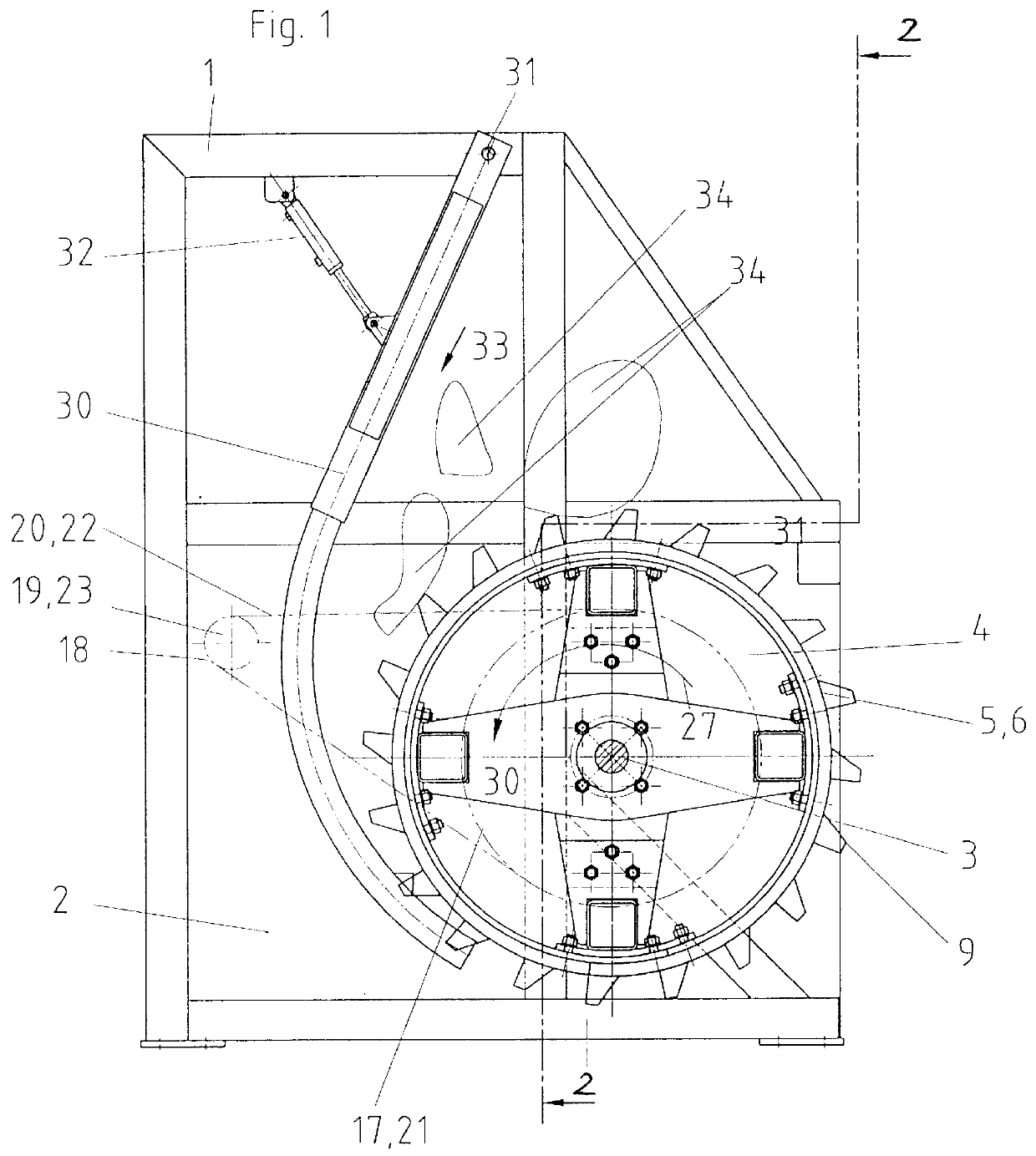
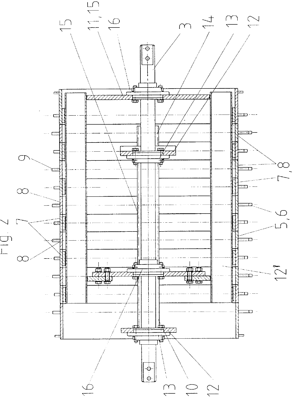
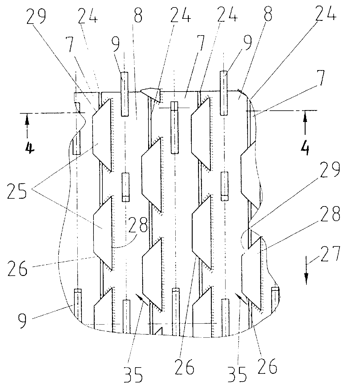
The device for ripping and tearing bags includes a frame 1, wherein the frame 1 is clad laterally with suitable wall parts 2. A shaft 3 is disposed at the frame 1. The ripping drum 4, formed as a drum-like element, is disposed on said shaft 3. The ripping drum 4 is formed of two drums 5 and 6 of annular strips 7, 8, said annular strips 7, 8 formed as rotary support elements, wherein the ripping elements 9 are disposed on the strips 7 and 8 of the strip drums 5 and 6. The two strip drums 5 and 6 are independently rotatably disposed on the shaft 3. Each strip drum 5 and 6 is comprised of the circumferential cylinder-shaped strips 7 or, respectively, 8, wherein the strips 7 and 8 are fixedly screwed to a supporting frame 10 or, respectively, 14. The first supporting frame 10 of the first strip drum 5 is comprised of braces 11, 12 and support rails 12', running parallel to the shaft 3. The braces 12 are disposed rotatably on the shaft 3 by means of a bearing 13. The second strip drum 6 ...


PUM


Abstract

A device for tearing and ripping bags comprising a plurality of driven, endless rotary support elements supporting tearing and ripping elements, wherein the rotary support elements are disposed sequentially along the axis of rotation. A plurality of covering and/or stripping elements is in each case disposed at least at one of the neighboring rotary support elements and the covering and/or stripping elements overlap at least in part a sequentially neighboring rotary support element. The covering and/or stripping elements on a rotary support element are aligned with the tangential motion advance direction in order to improve the device for preventing that long, tear-resistant pieces end up in the slot between the rotary support elements and bring the ripping device to a standstill based on a winding-up long tear-resistant pieces. For this purpose, the covering and/or stripping elements are disposed at a distance relative to each other.

Description

1. Field of the InventionThe invention relates to a device for ripping and tearing bags and / or for opening bags, wherein the device includes a plurality of driven, endless rotary support elements supporting ripping projections, wherein the rotary support elements are disposed sequentially along the axis of rotation.2. Brief Description of the Background of the Invention Including Prior ArtSuch a ripping device is known for example from the European printed patent document EP 0,686,562-A1 and has proven to be useful in practice. Bags are ripped open with this device in a surprisingly simple way. Jammings and windings of accompanying materials around the ripping drum are also excluded. However, a content of the bags of long and tear-resistant pieces presents problems, such as hemp strings or video tapes. These pieces end up in part in the slot between the rotary support elements.1. Purposes of the InventionIt is an object of the present invention to improve the ripping devices to prev...

Claims


Application Information

Patent Timeline
IPC IPC(8): B65B69/00B65F3/00
CPCB65B69/0008Y10S241/38
Inventor BAYER, MANFRED
Owner BAYER MANFRED
Why Eureka
Try Eureka