Antenna arrangements having radiating elements radiating at different frequencies

Inactive Publication Date: 2000-07-18
TELEFON AB LM ERICSSON (PUBL) +1
View PDF10 Cites 182 Cited by
  • Summary
  • Abstract
  • Description
  • Claims
  • Application Information

AI Technical Summary

Benefits of technology

It is an advantage of the invention that the existing infrastructure already provided for the 900 MHz frequency band can be used also for new frequency bands such as about 1800 MHz or 1900 MHz. It is also an advantage of the invention that the antenna elements or the radiating elements are simple and flexible and enables a simple feeding technique etc. A particular advantage is that the same kind of radiating elements can be used for both frequencies merely the size as given by the resonant dimensions, differing. It is also an advantage that dual polarisation states can be su

Problems solved by technology

However, for the operation of cellular mobile telecommunication systems a large number of base station antenna installations have been necessary.
However, the installation of base station antennas has caused protests among others from an esthetical point of view both on the countryside and in the cities.
Already the installation of masts with antennas for e.g. the 900 MHz frequency band has given rise to a lot of discussions and protests.
The installation of additional base station antenna arr

Method used


Image

  • Antenna arrangements having radiating elements radiating at different frequencies
  • Antenna arrangements having radiating elements radiating at different frequencies
  • Antenna arrangements having radiating elements radiating at different frequencies

Examples


Embodiment Construction

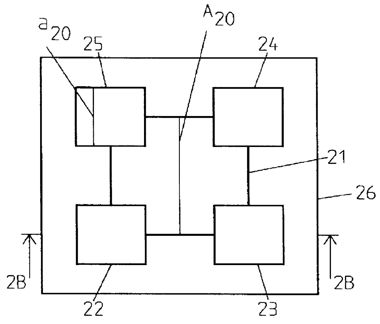
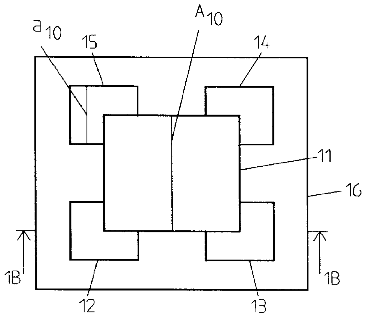
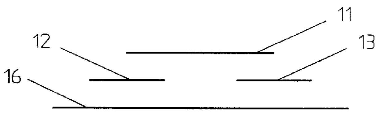
FIG. 1 shows a first example of a microstrip antenna arrangement 10 operating (receiving / transmitting) at two different frequencies or in two different frequency bands. In FIG. 1A, which is a top view of the antenna arrangement, 10 a first radiating element 11 is arranged on the top. The first radiating element 11 is here square shaped. Below the first radiating, element four second radiating elements 12,13,14,15 are arranged. The second radiating elements do of course not have to be arranged in a centralized manner under the corners of the first radiating element. They may also be arranged more closely (or vice versa) in one or both directions. This also applies for the embodiments to be described below with reference e.g. to FIGS. 3A,4A,5 etc. The first and second radiating elements respectively particularly comprise so called patch elements. A patch element is a patch of a conducting material, for example Cu. The second radiating elements 12,13,14,15 are symetrically arranged in ...


PUM


Abstract

An antenna arrangement includes a number of first radiating elements radiating in a first frequency band and a number of second radiating elements radiating in a second frequency band. The first and the second radiating elements are arranged in different planes. The second radiating elements are arranged in relation to the first radiating elements in such a way that each second radiating element partly overlaps the corresponding first radiating element. Each radiating element has at least one resonant dimension and the resonant dimension of the first radiating element is approximately twice the resonant dimension of the second radiating elements and the second radiating elements radiate at a frequency, or in a frequency band, which is approximately twice that of the first radiating element(s).

Description

BACKGROUNDThe present invention relates to an antenna arrangement comprising a number of radiating elements of which some radiate at a first frequency or in a first frequency band and some radiate at a second frequency or in a second frequency band so that one and the same antenna arrangement can be used for different frequencies or frequency bands.The invention also relates to a base station antenna arrangement that can be used for a first and a second frequency band so that one and the same base station antenna arrangement can be used for different mobile communication systems operating in different frequency bands.The field of mobile telecommunications is rapidly growing in a large number of countries and new markets and more countries are constantly introducing cellular communication systems. Furthermore new services and applications are continuously introduced on the, in every aspect, strongly expanding mobile telecommunication market. It is well known that a number systems ope...

Claims


Application Information

Patent Timeline
IPC IPC(8): H01Q9/04H01Q21/24H01Q5/00H01Q1/24H01Q21/30H01Q13/08
CPCH01Q1/246H01Q5/42H01Q21/24H01Q9/0457
Inventor DERNERYD, ANDERSJOHANSSON, MARTINSIPUS, ZVONIMIR
Owner TELEFON AB LM ERICSSON (PUBL)
Why Eureka
Try Eureka