Cooling of avionics using a fuel tank and refrigerant source

a technology of fuel tank and avionics, which is applied in the field of cooling of avionics and/or power electronics, can solve the problems of unsuitability for avionics cooling, limited heat transfer, and high energy consumption of air cooling of avionics, and achieve the effect of simple and flexibl

Active Publication Date: 2011-10-25
SAAB AB
View PDF10 Cites 19 Cited by
  • Summary
  • Abstract
  • Description
  • Claims
  • Application Information

AI Technical Summary

Benefits of technology

[0008]The object of the present invention is thus to provide a simple and flexible avionics cooling system, that is adapted to take account of variations in the avionics heat load.

Problems solved by technology

The avionics must be cooled constantly or they will overheat.
Air cooling of avionics is very energy consuming.
However only a limited amount of heat can be transferred to the fuel, without reaching the upper limit of the fuel temperature, or that the fuel temperature raises such that it becomes unsuitable for avionics cooling.
However, it does not take account to conditions that may arise due to variations in the heat load of the avionics.
The system is also quite complicated.

Method used


Image

  • Cooling of avionics using a fuel tank and refrigerant source
  • Cooling of avionics using a fuel tank and refrigerant source
  • Cooling of avionics using a fuel tank and refrigerant source

Examples


example

[0032]The following example is a temperature level study for the combined fuel and vapour cycle system of the present invention. The example, which is intended for illustrative purpose only, shows how the three sub-systems of the cooling system interacts at different temperatures of the fuel in the fuel tank.

[0033]The study was based on the following parameters:

Fluid characteristics: Fuel thermal capacity (cp)=2140 J / (kg*K)) at 40° C.

[0034]PAO thermal capacity (cp)=1950 J / (kg*K)) at 40° C.

Heat Load from Avionics: 10 kW (heat generated by pumps not included)

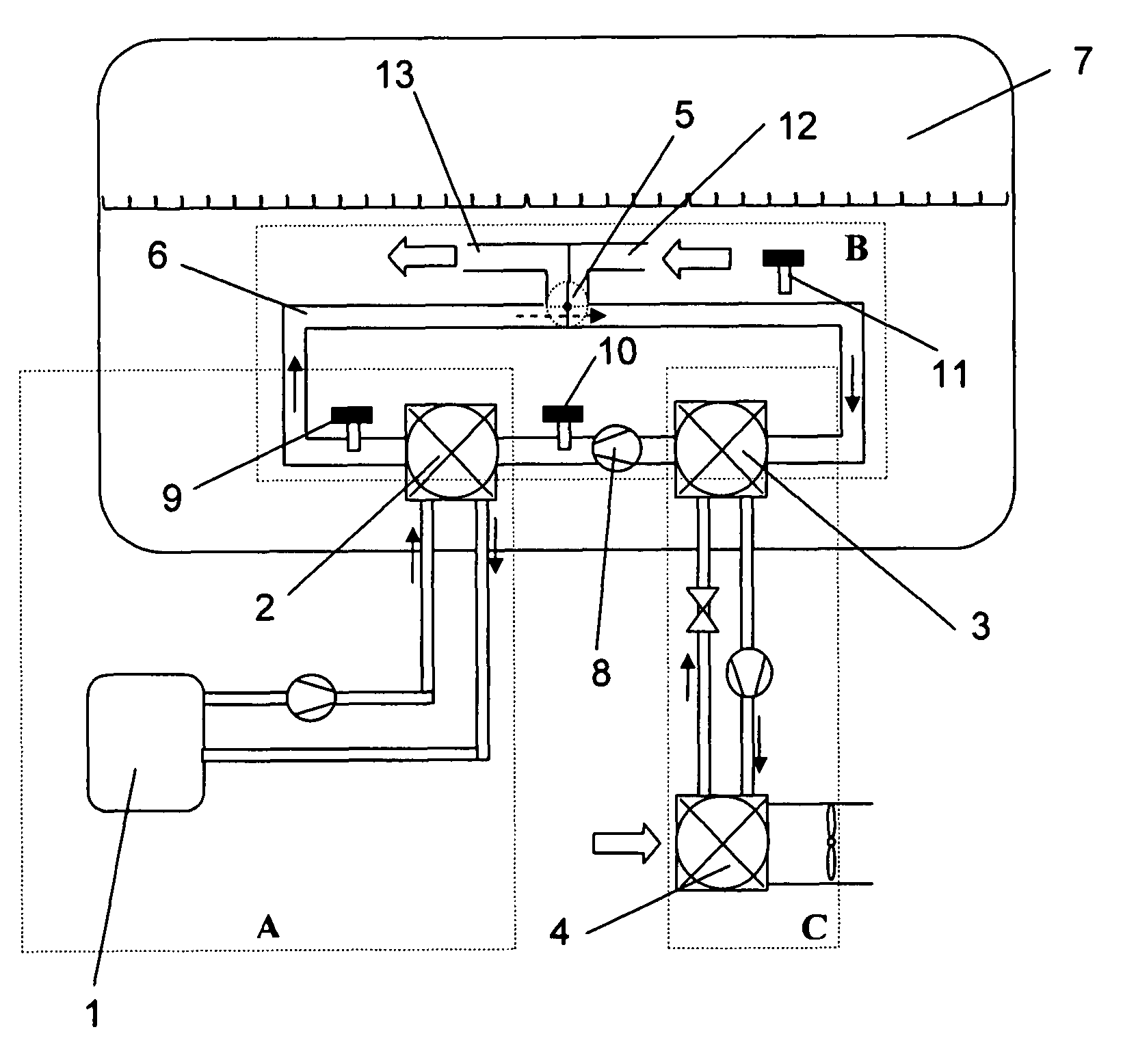
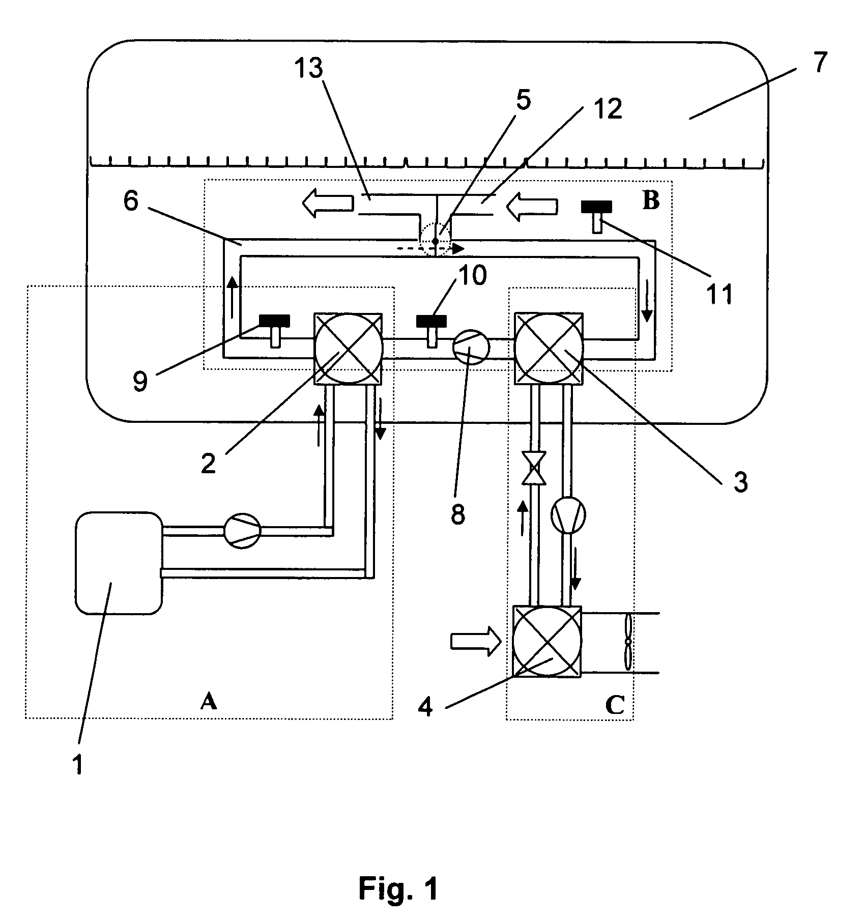
[0035]The temperature requirements of the system were set as shown in Table 1, wherein reference numerals refer to FIG. 1.

[0036]

TABLE 1Heat exchanger / fluidInlet temp. (° C.)Outlet temp. (° C.)Avionics Bay Cooling (1) / PAOFuel Heat Exch. (2) / PAOFuel Heat Exch. (2) / fuel—a)Evaporator (3) / fuelFuel tank temp.and a)no temperature requirement for the outlet fuel temperature

[0037]The result of the study is shown in Table 2. Reference numer...


PUM


Abstract

An avionics cooling system including an avionics cooling circuit operating with a liquid coolant; a fuel circuit; and a vapor cooling cycle operating with a refrigerant. The avionics cooling circuit transfers heat withdrawn from avionics to the fuel circuit, whereby the heat is dumped into fuel, and the vapor cooling cycle transfers heat that cannot be dumped into the fuel from the fuel circuit to ram air.

Description

CROSS-REFERENCE TO RELATED APPLICATIONS[0001]This application claims priority to European patent application 06121199.1 filed 25 Sep. 2006.TECHNICAL FIELD[0002]An avionics and / or power electronics cooling circuit operating with a coolant is flexibly connected to a vapour cooling cycle by means of a fuel circuit.BACKGROUND[0003]The technical field of the present invention relates to cooling of avionics and / or power electronics, i.e. electronics designed for use in aerospace vehicles, such as aircraft electronics. The avionics must be cooled constantly or they will overheat. Fuel or air cooling cycles are typically used for cooling of avionics. In rare cases vapour cooling circuits are used.[0004]Air cooling circuits utilise compressed air from the aircraft engine, which is converted to be suitable for avionics cooling (temperature, pressure and humidity), and for keeping the cabin environment comfortable and pressurised. Air cooling of avionics is very energy consuming. The coefficie...

Claims


Application Information

Patent Timeline
Patent Type & Authority Patents(United States)
IPC IPC(8): F25B19/00
CPCB64D13/00B64D37/34B64D2013/0614B64D2013/0674Y02T50/56B64D2013/0659Y02T50/50
Inventor JARLESTAL, ANDERS
Owner SAAB AB
Why Eureka
Try Eureka