Three person bicycle

a three-person bicycle and bicycle technology, applied in the direction of bicycles, vehicle components, rider propulsion, etc., can solve the problems of increasing the cyclical load stress on the frame, absorbing valuable rider energy, and shortening the wheelbase. , the effect of large turning radius

Inactive Publication Date: 2000-08-01
GRAHAM SEAN
View PDF3 Cites 11 Cited by
  • Summary
  • Abstract
  • Description
  • Claims
  • Application Information

AI Technical Summary

Benefits of technology

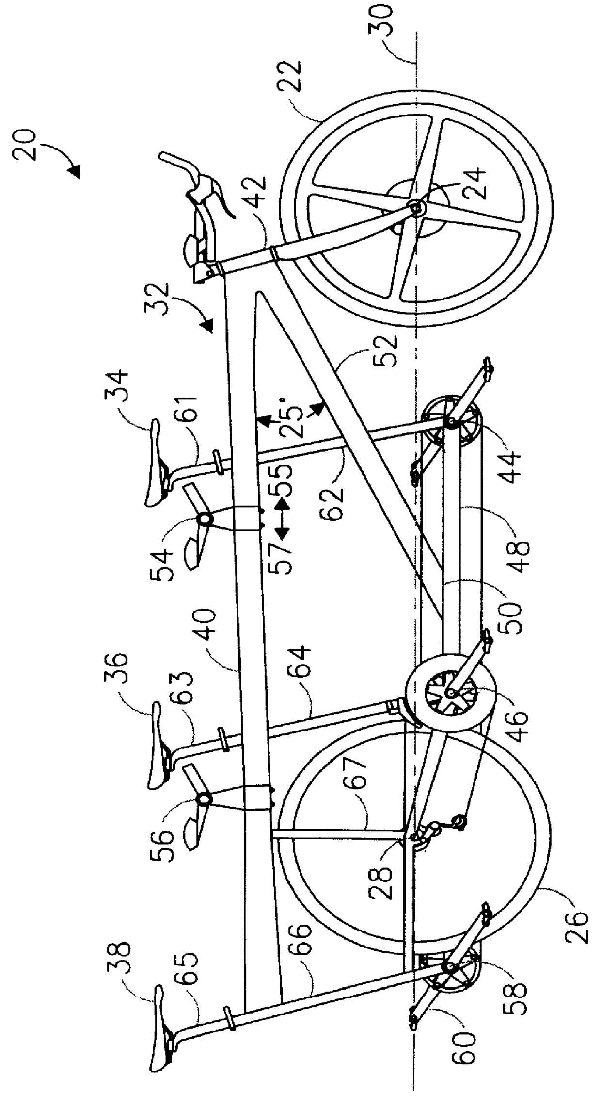
The present invention is directed to an improved three-person bicycle which overcomes the difficulties encountered with long wheelbases. In the present invention, the wheelbase is shortened by placing the rear wheel between the second and third riders. In this configuration, the bicycle handles like a two-person (tandem) bicycle, but has the power 
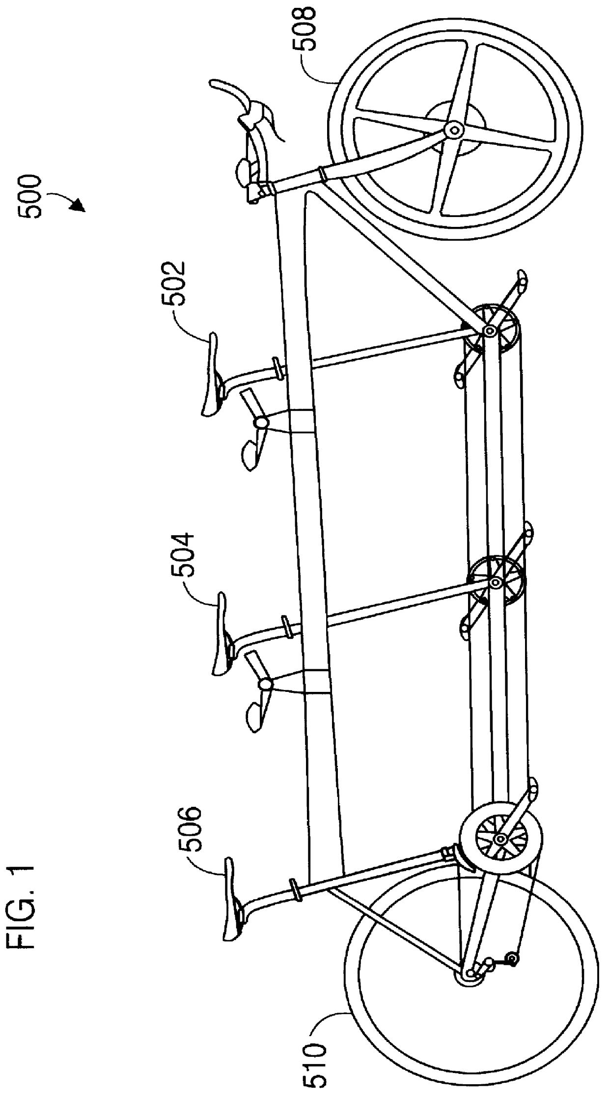
advantage a third rider. With the rear wheel positioned behind the third rider as in FIG. 1, the bicycle has a large turning radius which renders it difficult to steer, control, and balance. Conversely, the shortened wheelbase of the present invention reduces the turning radius so that the bicycle handles exactly like a tandem. The response of the present invention to the controlling actions of the riders is more pronounced, making the bicycle considerably easier to balance and steer. An objective of the present invention is to break long distance human powered speed records. A proposed name for the present invention is TRIDEM.
The placement of the second wheel between the second and third riders also improves the structural properties of the present invention. By supporting the rear of the frame between the second and third riders, the weight of the riders is advantageously distributed across the frame truss. Flexing in the middle of the frame of the present invention is greatly reduced, as compared to the high flexing of the FIG. 1 frame (caused by the longer wheelbase). The high flexing of the longer wheelbase bicycle has two major disadvantages. First, it increases the cyclical loading fatigue stresses on the frame. And second, valuable rider energy is absorbed by the dampening of vibrations within the flexing frame. The present invention reduces flexing and therefore mitigates these two disadvantages. Additionally, the frame of the present invention can be constructed with less material, thereby reducing weight and increasing performance. One might think that this design could lead to the bicycle "wheelieing", or not placing sufficient pressure on the front wheel. Although, about 70% of the bicycle's weight is supported on the rear wheel, the front wheel still supports a minimum of about 70 lbs. even if all three riders are leaning back as far as possible.
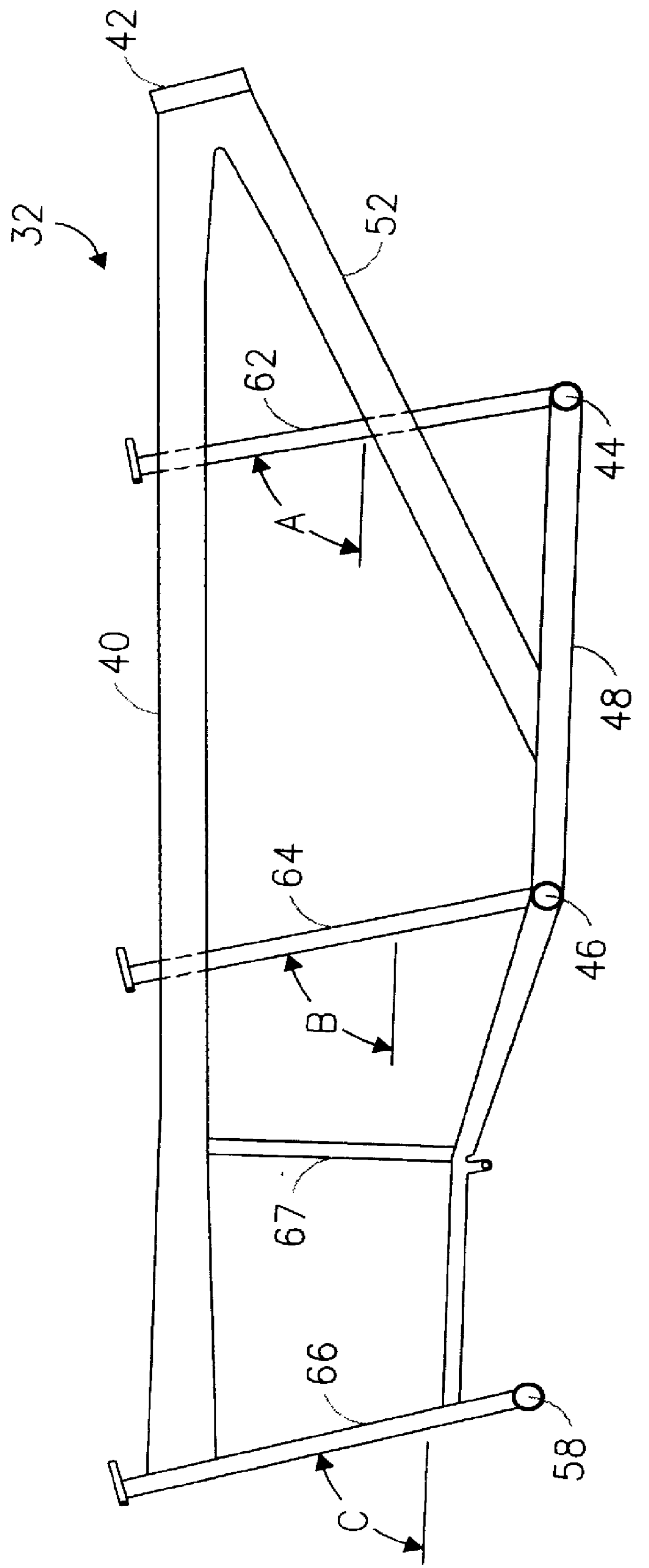
Another unique feature of the present invention is a down tube which extends from the head tube to the bottom connection tube between the first and second crank housings. The down tube contributes to the both the vertical and lateral stiffness of the bicycle, while additionally providing support to the front drive train. The resulting frame truss configuration is considerably stronger and less flexible than those designed with a standard down tube as in FIG. 1.
The present invention also includes movable handle bar supports for the second and third riders. These movable supports, which can be selectively positioned along the crossbar, allow the bicycle to be quickly and easily modified to accommodate riders of different sizes (such as small children, by positioning the supports toward the associated seat). This feature is also useful in long distance riding wherein a rider rotation scheme is employed. The handle bar supports for the first and second riding positions can be quickly and easily adjusted to suit the needs of the individual riders.
The present invention additionally incorporates a crank mechanism for the third rider, wherein the third rider can rest his / her legs while the other riders pedal. This yields advantages in long distance rides when a rider rotation scheme is utilized to maximize performance.
The present invention also includes first, second, and third seat tubes for the front, middle and rear riders respectively which form progressively decreasing angles with the horizontal. The first seat tube is the most vertical, the rear seat tube is the most horizontal, with the second seat tube having an angle between the two. This unique configuration optimizes the performance of the riders on a rotation scheme. Each position on the bicycle has a slightly different geometry and feel to the rider. Therefore, by periodically switching positions on the bicycle, the riders can endure longer because each position works the riders muscles in a slightly different way. The front position with its steep angled seat tube places the rider in an aggressive aerodynamic position like that of a sprint bicycle. The geometry of the rear position is more conducive to relaxed distance riding.

Problems solved by technology

With the rear wheel positioned behind the third rider as in FIG. 1, the bicycle has a large turning radius which renders it difficult to steer, control, and balance.
First, it increases the cyclical loading fatigue stresses on the frame.
And second, valuable rider energy is absorbed by the dampening of vibrations within the flexing frame.
One might think that this design could lead to the bicycle "wheelieing", or not placing sufficient pressure on the front wheel.

Method used


Image

  • Three person bicycle
  • Three person bicycle
  • Three person bicycle

Examples


Embodiment Construction

Referring initially to FIG. 1, there is illustrated a side elevation view of a three-person bicycle 500 wherein all of the riders are positioned on seats 502, 504, and 506 which are located between the front and rear wheels 508 and 510.

Referring now to FIG. 2, there is illustrated a side elevation view of a three-person bicycle in accordance with the present invention, generally designated as 20. FIG. 3 is an enlarged side elevation view of the frame 32 of bicycle 20. Because of the placement of the third rider behind the rear wheel, bicycle 20 has the wheelbase of a tandem bicycle with a three-rider capacity. Bicycle 20 includes a front wheel 22 having a front axle 24, a rear wheel 26 having a rear axle 28, and a longitudinal axis 30 passing between the front and rear axles 24 and 28 respectively. A frame 32 connects front wheel 22 and rear wheel 26. A first seat 34 is longitudinally disposed upon frame 32 between front axle 24 and rear axle 28 (as measured parallel to longitudinal...


PUM


Abstract

A three-person bicycle (20) having two of the riding positions situated between a front wheel (22) and a rear wheel (26), and the third riding position situated behind the rear wheel (26). Bicycle (20) includes a front first seat (34), a middle second seat (36), and a third rear seat (38) connected to a frame (32). Front seat (34) and second seat (36) are located on frame (32) between front axle (24) and rear axle (28). Third rear seat (38) is connected to frame (32) behind rear axle (28) and rear wheel (26).

Description

The present invention pertains to bicycles, and in particular to a bicycle which is ridden by three people, and is specifically designed to maintain high speeds for prolonged periods of time.Bicycles of a multitude of styles, shapes, and sizes are well known in the art. Bicycles are the fastest and most popular means of human powered transportation, and are capable of sustaining speeds of nearly 35 miles per hour over flat ground. Millions of dollars are spent every year in an attempt to develop faster bicycles. Three basic factors affect the speed at which a bicycle travels. These are: (1) the amount of power delivered by the rider(s), (2) the frictional forces acting upon the bicycle (wind, rolling and mechanical drag), and (3) the weight of the bicycle and rider(s). Therefore, to create the fastest bicycle possible, power and aerodynamics must be maximized, while friction and weight must be minimized. The power input is controlled by the number and physical condition of the rider...

Claims


Application Information

Patent Timeline
Patent Type & Authority Patents(United States)
IPC IPC(8): B62K3/00B62K3/12
CPCB62K3/12
Inventor GRAHAM, SEAN
Owner GRAHAM SEAN
Why Eureka
Try Eureka