Resistivity log correction method

a technology of resistivity log and correction method, which is applied in the direction of seismology, water-logging using reradiation, instruments, etc., can solve the problems of inability to accurately represent the formation resistivity of resistivity, rarely reading resistivity log, and time-consuming

Inactive Publication Date: 2000-08-01
SHELL OIL CO
View PDF9 Cites 18 Cited by
  • Summary
  • Abstract
  • Description
  • Claims
  • Application Information

AI Technical Summary

Problems solved by technology

However, a resistivity log seldom reads the true formation resistivities, which are the resistivities of the undisturbed formation in the so-called virgin zone away from the borehole.
However, in most cases the disturbing effects are simultaneously present and interweaved in such a way that adding of the individual corrections does not lead to the true formation resistivity.
A drawback of the known method is that no invasion of wellbore fluid into the formation is taken into account and that therefore the obtained resistiv...

Method used


Image

  • Resistivity log correction method
  • Resistivity log correction method

Examples


Embodiment Construction

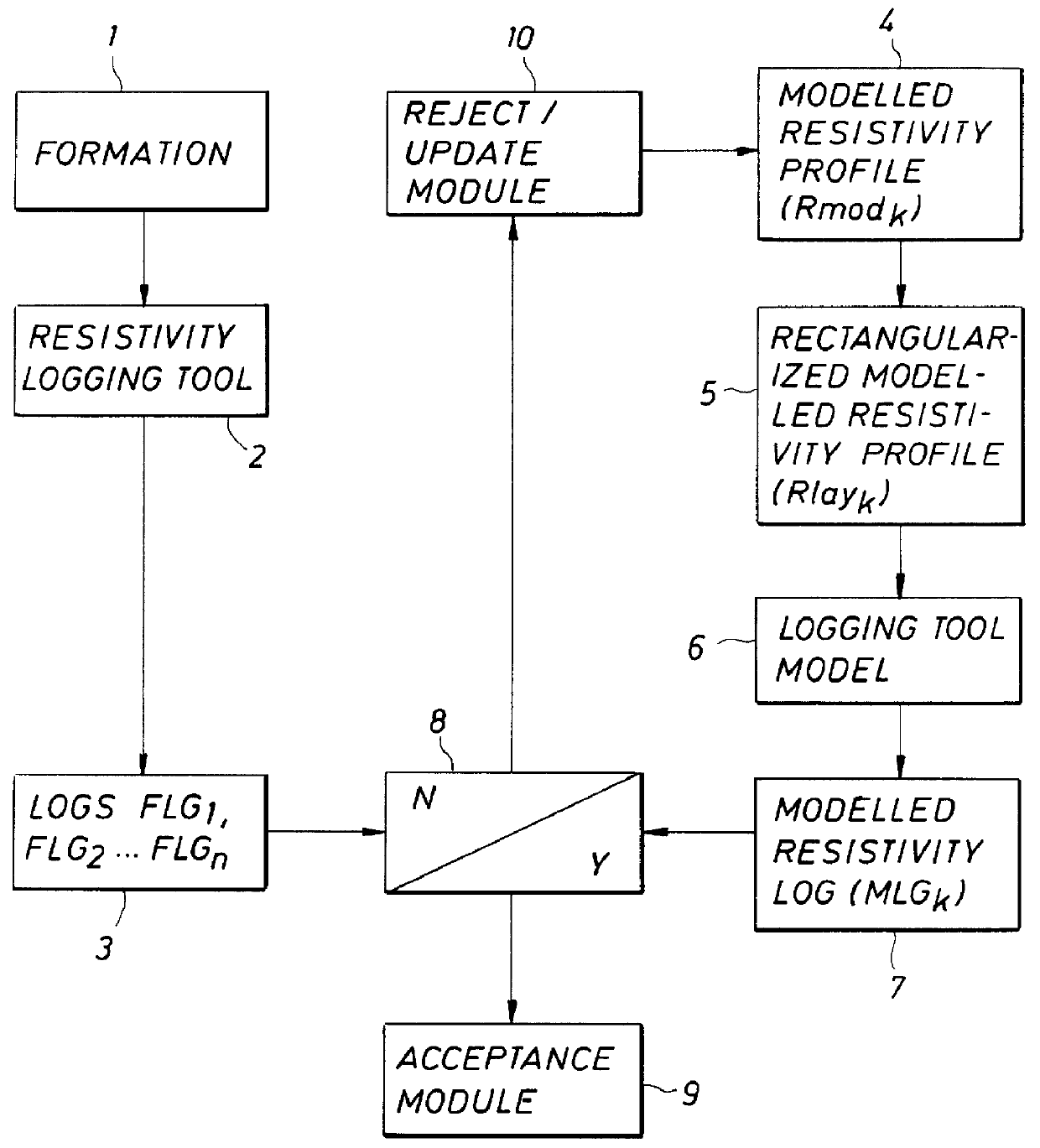
Reference is now made to FIG. 1 showing an inversion scheme for iterated forward modelling of a resistivity profile of an earth formation 1 provided with a wellbore (not shown) in which a resistivity logging tool 2 is arranged.

In applying the method of the invention the resistivity logging tool 2 is operated in the wellbore to provide resistivity logs (FLG.sub.1, FLG.sub.2, . . . , FLG.sub.n) 3 of different radial distance intervals of the earth formation surrounding the wellbore. The wellbore is filled with a wellbore fluid which penetrates the surrounding earth formation to a certain radial distance. The radial distance intervals start at the wellbore wall and extend to a radius which exceeds the expected depth of penetration of the wellbore fluid by a suitable distance. The logging tool thereby provides a plurality of resistivity logs (FLG.sub.1, FLG.sub.2, . . . , FLG.sub.n) 3, one for each radial distance interval k. The resistivities in the various radial distance intervals k ...


PUM


Abstract

A method of determining electric resistivity of an earth formation (1) surrounding a wellbore filled with a wellbore fluid, is provided, which method comprises: operating a resistivity logging tool (2) in the wellbore so as to provide a plurality of resistivity logs (FLG1, . . . , n) (3) of the earth formation (1) for different radial intervals (1, . . . , n) relative to the wellbore; for each radial interval (k), selecting a modelled resistivity profile (Rmodk) (4); inputting the modelled resistivity profiles (Rmod1, . . . , n) (4) to a logging tool simulator (6) so as to provide for each radial interval (k) a modelled resistivity log (MLGk) (7) having a depth of investigation corresponding to the radial interval (k); for each radial interval (k) updating the modelled resistivity profile (Rmodk) (7) in dependence of an observed deviation of the resistivity log (FLGk) (3) from the modelled resistivity log (MLGk) (7); and repeating steps c)-d) until for each radial interval (k) the difference between the resistivity log (FLGk) (3) and the corresponding modelled resistivity log (MLGk) (7) is below a selected threshold value (8).

Description

The present invention relates to a method of logging of an earth formation surrounding a wellbore filled with a wellbore fluid.BACKGROUND TO THE INVENTIONA common method of earth formation logging is resistivity logging in which an electric current is injected or induced in the earth formation and the resulting voltage is determined to provide a resistivity log, which is a measure of the resistivity of the formation as a function of depth. However, a resistivity log seldom reads the true formation resistivities, which are the resistivities of the undisturbed formation in the so-called virgin zone away from the borehole. The resistivity log is influenced by disturbing effects such as the presence of the borehole, invasion of wellbore fluid into the formation (mud-filtrate invasion) and the presence of adjacent earth layers (the so-called shoulder beds). In case one of these effects dominates over the other, so-called correction charts may be used to correct the log for the dominating...

Claims


Application Information

Patent Timeline
IPC IPC(8): G01V3/20G01V3/18G01V3/38
CPCG01V3/20
Inventor HAKVOORT, RICHARD GERRITKOELMAN, JOHANNES MARIA VIANNEY ANTONIUS
Owner SHELL OIL CO
Why Eureka
Try Eureka