C-clamp

a c-clamp and clamping technology, applied in the field of c-clamps, can solve the problem of inconvenient adjustment of the conventional c-clamps

Inactive Publication Date: 2000-08-08
AMARILLO HARDWARE +1
View PDF14 Cites 47 Cited by
  • Summary
  • Abstract
  • Description
  • Claims
  • Application Information

AI Technical Summary

Problems solved by technology

Because screw speed is limited by the pitch of the threads formed within the threaded bore, adjustment of the conventional C-clamp is undesirably slow.

Method used


Image

  • C-clamp
  • C-clamp
  • C-clamp

Examples


Embodiment Construction

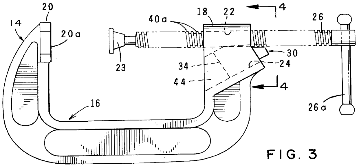
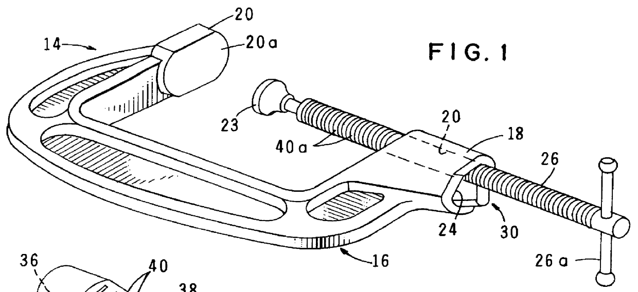
Referring to the drawings, and particularly to FIGS. 1 through 3, one form of the article clamping device of the present invention for clamping a work piece between the jaws of the C-Clamp is there shown and generally designated by the Numeral 14. The device of this form of the invention comprises a generally "C" shaped frame 16, having first and second end portions 18 and 20. As best seen in FIG. 3, end portion 20 includes a work piece engaging flat 20a. End portion 18, on the other hand, includes a first through bore 22 and a second, angularly extending, larger diameter cavity defining bore 24, which extends angularly relative to the axis of through bore 22. A threaded rod 26 is receivable through bore 22 for telescopic movement therewithin between a first retracted position and a second extended position.

Provided at the inboard end of rod 26 is a work piece engaging swivel 23. Forming an extremely important aspect of the apparatus of the invention is control means for controlling...


PUM


Abstract

A clamping device including a generally C-shaped frame having first and second ends. The first end of the C-shaped frame is uniquely provided with a first through bore and a second angularly extending bore. The device further includes an elongated threaded rod having an external thread and being telescopically movable within the through bore. A novel control member having a rack-like upper surface is disposed within the second bore of the C-clamp frame for movement into and out of the engagement with the threaded rod in response to manual force exerted on the control member and also in response to forces exerted on the out-board end of the threaded rod urging it in a direction toward engagement with the work piece.

Description

1. Field of the InventionThe present invention relates generally to clamping devices. More particularly, the invention concerns a quick set and release C-clamp.2. Discussion of the Prior ArtC-clamps are old in the art. The conventional C-clamp comprises a generally C-shaped frame having a first end provided with a threaded bore and a second, opposite end provided with a flat, object engaging surface. An elongated threaded screw is threadably relievable within the threaded bore and includes an object engaging end which cooperates with the flat object engaging surface of the C-shaped frame to clamp an article within the throat of the C-clamp. Adjustment of this common type of C-clamp is accomplished by rotating the threaded screw into and out of the threaded bore. Because screw speed is limited by the pitch of the threads formed within the threaded bore, adjustment of the conventional C-clamp is undesirably slow. For this reason a number of different types of quick set and release C-c...

Claims


Application Information

Patent Timeline
Patent Type & Authority Patents(United States)
IPC IPC(8): B25B5/10B25B5/00
CPCB25B5/10B25B5/101
Inventor KHACHATOORIAN, ZAREH
Owner AMARILLO HARDWARE
Why Eureka
Try Eureka