

Structure of output section of jet propulsion engine or gas turbine
a jet propulsion engine and output section technology, applied in the direction of machines/engines, liquid fuel engines, supersonic fluid pumps, etc., can solve the problems of limited engine speed and increased blade width of propeller blades
Inactive Publication Date: 2000-08-08
KAWASAKI HEAVY IND LTD
View PDF15 Cites 27 Cited by
- Summary
- Abstract
- Description
- Claims
- Application Information
AI Technical Summary
Problems solved by technology
In other words, there is a problem that the engine speed is limited.
Currently, a width of a blade such as a pr
Method used
View moreImage
Smart ImageViewing Examples

Examples
 PUM
 Abstract
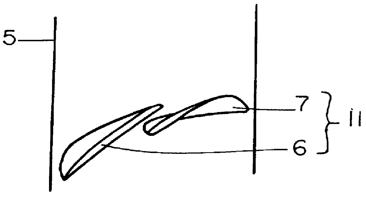
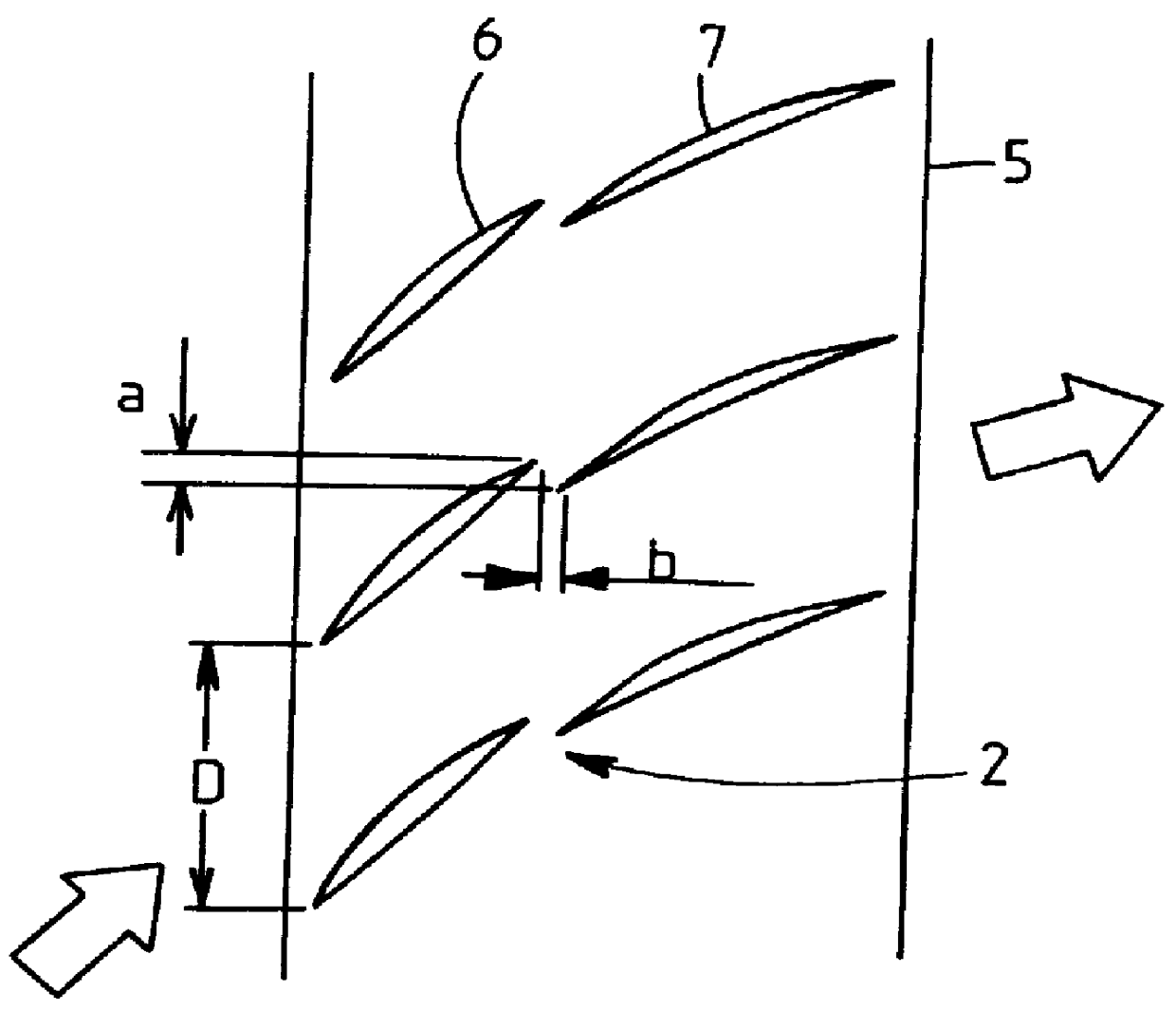
A tandem blade lattice having characteristics enhanced is provided. In a high pressure ratio blade lattice, inevitable generation of an shock wave is shifted, as much as possible, toward a rear portion of an upper surface of a front blade to inhibit separation from a blade surface from being caused by interference of the shock wave and a boundary layer, and boundary layer control is performed such that a speed, a momentum and the like of a jet flowing from a trailing edge of a lower surface of the front blade onto an upper surface of a rear blade are regulated to obtain a flow along the upper surface of the rear blade, so that separation of the boundary layer on the upper surface of the rear blade is restricted to a vicinity of a trailing edge.
Description
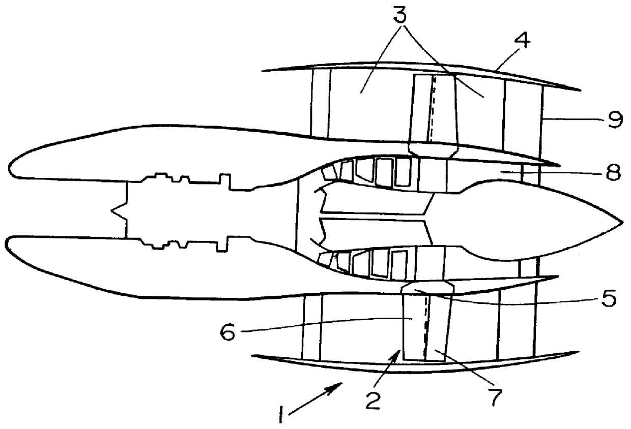
The present invention relates to a structure of an output section of a jet propulsion engine or a gas turbine, and a tandem blade lattice, and more particularly to a structure of an output section of a jet propulsion engine or a gas turbine which can conventionally rotate at a higher speed than in the prior art and a tandem blade lattice suitable for the structure of the output section.DESCRIPTION OF BACKGROUND ARTIn the prior part, various proposals have been made in order to enhance outputs of a jet propulsion engine such as a turbojet engine, turbofan jet engine, a turboshaft engine, a ram-jet engine or an air turbo ram-jet engine and gas turbine. As an example of the proposals, an advanced turboprop engine (hereinafter referred to as an ATP) to have a bypass ratio of about 40 to 50 has been proposed (see page 16 and the like of "THE JET ENGINE" written by Rolls-Royce pic, publication of Japan Air Technical Association Co.) As shown in FIG. 14, for example, it has been planned th...
Claims
Login to View More Application Information
Patent Timeline
 IPC IPC(8): F01D9/04F01D5/14F02K3/04
CPCF01D5/142F01D5/146F01D9/041F04D29/544F04D29/542Y02T50/673Y10S415/914Y02T50/671F04D21/00Y02T50/60
InventorHASHIMOTO, KEISUKE
OwnerKAWASAKI HEAVY IND LTD