Apparatus and methods for moving a working fluid by contact with a transport fluid

a technology of working fluid and moving apparatus, which is applied in the direction of transportation and packaging, machines/engines, instruments, etc., can solve the problems of reducing achieving shock wave across a restricted section, and limiting the size of any particulate throughput, etc., to achieve constant cross section and constant cross section

Active Publication Date: 2006-09-26
TYCO FIRE PRODS LP +1
View PDF32 Cites 66 Cited by
  • Summary
  • Abstract
  • Description
  • Claims
  • Application Information

AI Technical Summary

Benefits of technology

[0036]The fluid mover of the present invention may also be used in heating applications where the heat in the case of steam when used as the transport fluid is employed since necessarily the working fluid will receive heat from the steam. The heat of the steam may also have advantageous effects on the physical properties of the working fluid; for example the viscosity of the working fluid may be reduced.
[0037]According to a third aspect of the present invention a method of moving a working fluid includes presenting a fluid mover to the fluid, the mover having a straight-through passage of substantially constant cross section, applying a substantially circumscribing stream of a transport fluid to the passage through an annular nozzle, causing the collapse of the transport fluid thereof to create a region of low pressure thereby to induce working fluid flow through the passage (3), generating a supersonic shock wave within the passage downstream of the nozzle, inducing flow of the working fluid through the passage from an inlet to an outlet thereof, and modulating the shock wave to vary the working fluid discharge from the outlet.
[0038]The transport fluid is preferably a condensable fluid and may be a gas or vapour, for example steam.
[0039]According to a fourth aspect of the present invention a method of moving a working fluid includes presenting a fluid mover to the fluid, the mover having a straight-through passage of substantially constant cross section, applying a substantially circumscribing stream of steam to the passage through an annular nozzle, causing the collapse of the steam by virtue of condensation thereof to create a region of low pressure thereby to induce working fluid flow through the passage (3), generating a supersonic shock wave within the passage downstream of the nozzle, inducing flow of the working fluid through the passage from an inlet to an outlet thereof, modulating the shock wave to vary the working fluid discharge from the outlet.
[0040]The thermal capacity of the working fluid is generally sufficient to yield the desired result in terms of the condensation effect. However, in those instances where that capacity might be insufficient, the invention includes the step of introducing additional working fluid or another working fluid, e.g. water, at a location downstream of the introduction of the transport fluid, e.g. steam, in order to provide additional quenching of the steam to give the requisite result.
[0041]The method of the present invention involves the transfer of energy to the working fluid by a combination of heat, momentum and mass transfer as the transport fluid, e.g. steam, is accelerated to supersonic speeds and directed by the nozzle into the working or process fluid. The resulting mixture of the transport and working fluids is accelerated within the pseudo-convergent section before it decelerates as a result of shear losses, steam condensation, and mass transfer. It is the decelerative aspect of the invention that results in the generation of the supersonic shock wave.

Problems solved by technology

One of the major limitations of the conventional convergent / divergent systems is that their performance is very sensitive to the position of the shock wave which tends to be unstable, easily moving away from its optimum position.
Such systems can also only achieve a shock wave across a restricted section.
Furthermore, for systems which employ a central steam nozzle, the throat dimension restriction and the sharp change of direction affecting the process fluid presents a serious limitation on the size of any particulate throughput and certainly any rogue material that might enter the system could cause blockage.
It is to be noted that the flow of material whilst being assisted through the throat body has to pass from a wide bore nipple into a tapered section prior to the location of the primary steam nozzle, thus constraining the material and potentially causing blockages.
The potential disadvantage of the Schwarz system is that by virtue of the convergent nature of the inlet to the unit and the constricted throat portion the free flow of fluid materials therethrough is likely to be difficult or restricted by the physical characteristics of the materials.
As will be appreciated control on the type and size of material entering this system is difficult and the chances of blockage are high from material or agglomerates which have a size approaching the inlet bore size of the unit.
In particular the problem associated with this type of pump, used for pumping gas, resides in controlling the positioning of the shock wave which is critical in that if it moves into either the intake or the discharge zone of the diffusor, significant difficulties arise.
In particular, if the shock wave moves into the convergent conical intake zone the jet pump becomes unstable and might even fail.
If the shock wave moves into the divergent conical exit zone the rate of flow of the mixture of the thrust and suction streams is accelerated resulting in a reduction in efficiency.
This jet pump is configured for gas pumping and as such would be unsuitable for pumping liquids or liquid / solids mixtures, not least because of the significant difficulties associated with achieving supersonic velocities with substantially incompressible fluids.
Clearly the amount of energy that would be required to impart supersonic velocity to the mixture would be prohibitive since the performance would be poor.
The combination of the shearing mechanism, the shockwave and the heat input will destroy water borne organisms such as snails and artemia.
This effect could be further enhanced with the introduction of air to the working fluid, thereby causing gas bubble trauma and / or gas saturation.

Method used


Image

  • Apparatus and methods for moving a working fluid by contact with a transport fluid
  • Apparatus and methods for moving a working fluid by contact with a transport fluid
  • Apparatus and methods for moving a working fluid by contact with a transport fluid

Examples


example

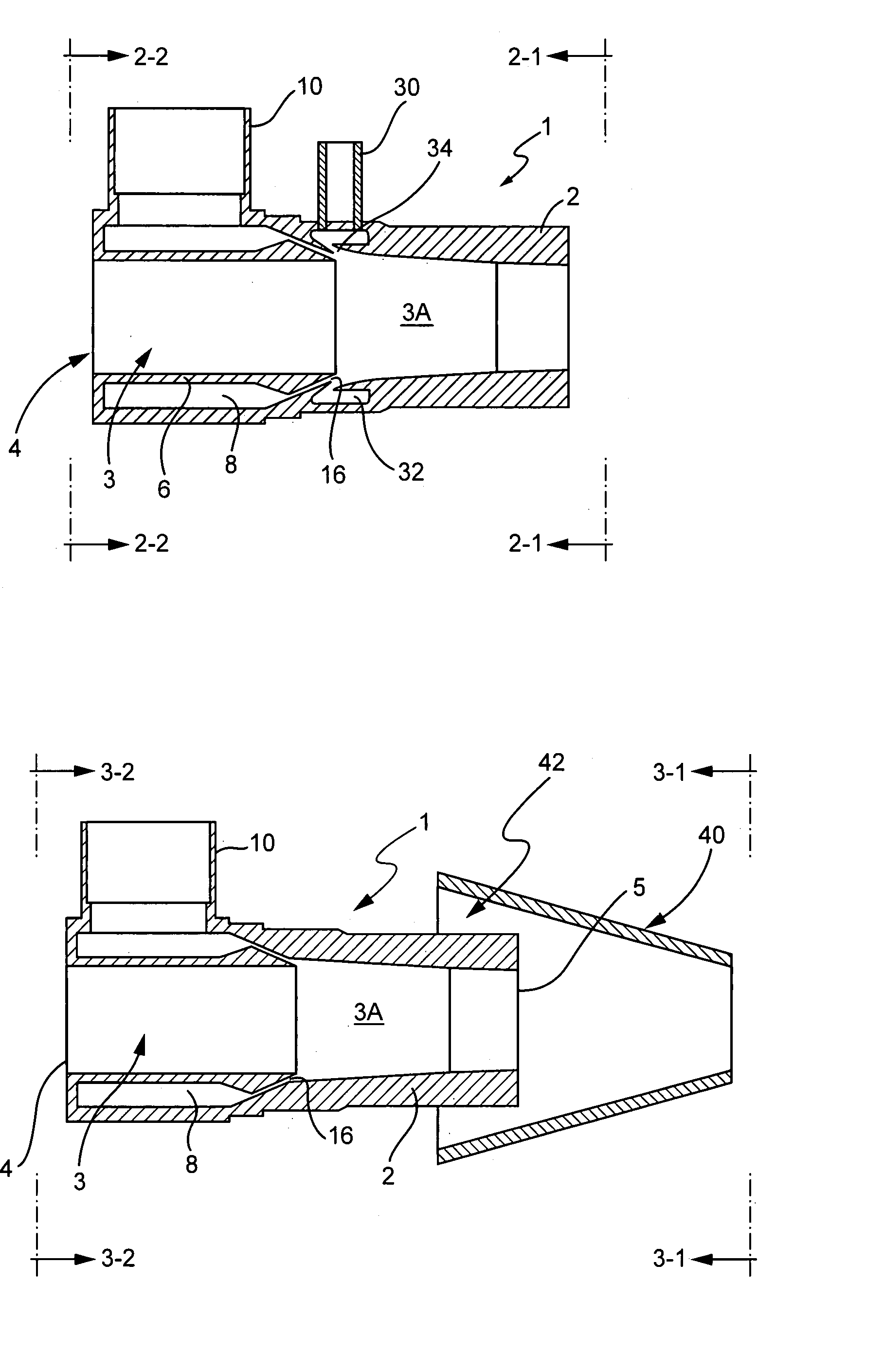
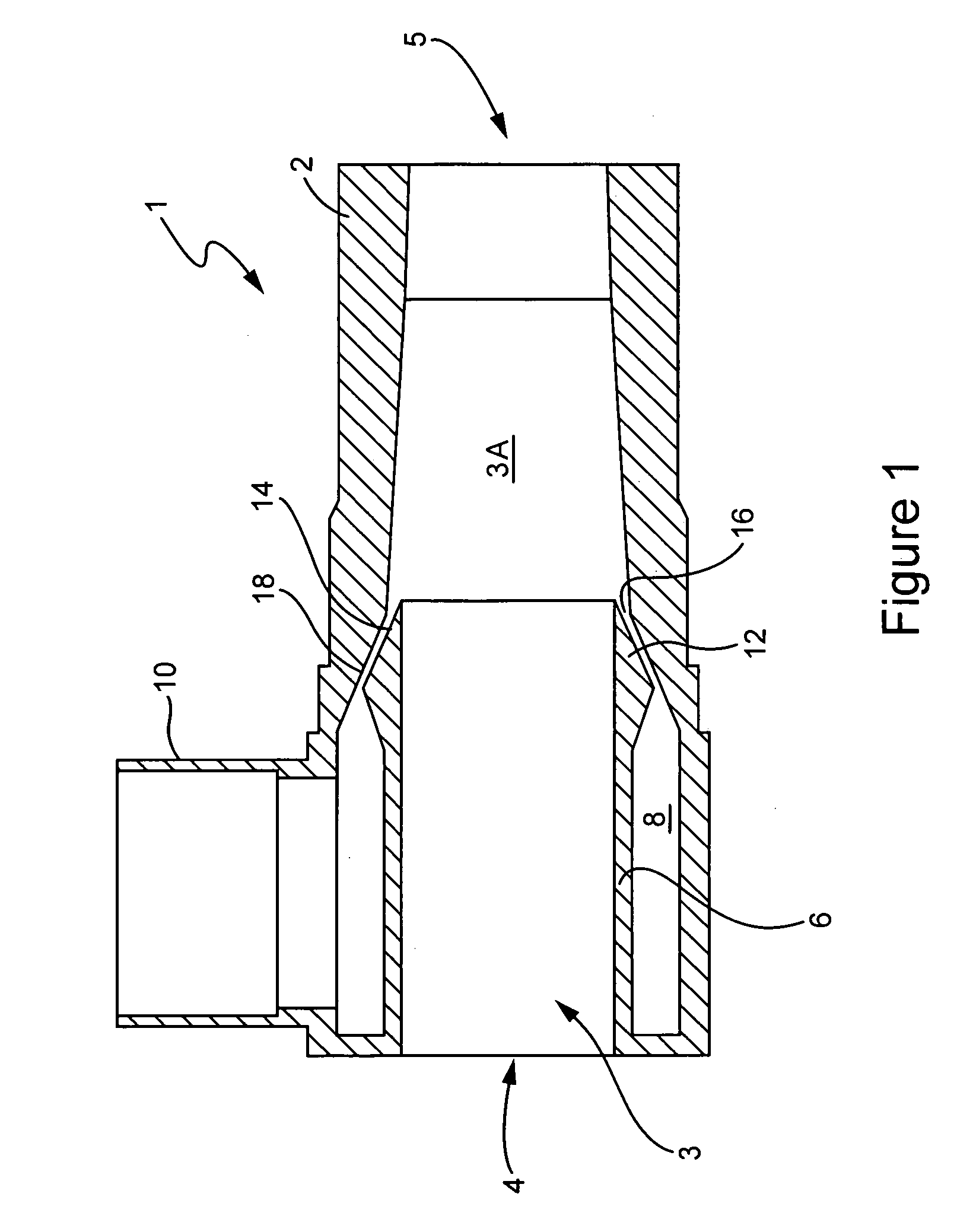
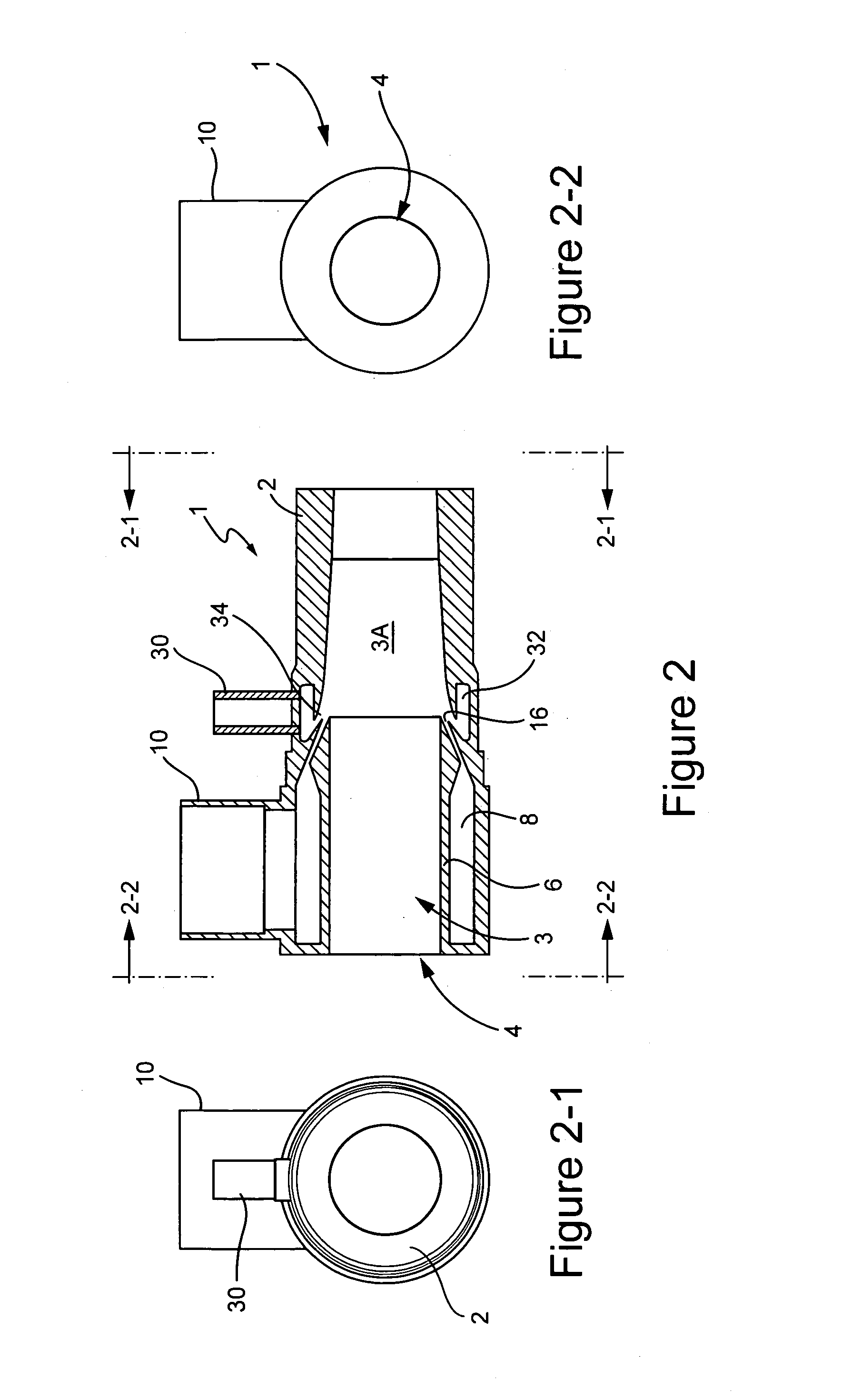
[0077]By way of example only, we have designed a fluid mover (1) having a central passage (3A) bore of 47 mm for use at 5 bar gauge of steam with a dryness of 99%, the annular nozzle having an area ratio of 1.9 with an included angle of 5.7° and a throat gap of 1.34 mm. The angle at which the nozzle is orientated in relation to the axis of the flow passage (3) and that of the mixing chamber (3A) is 24°. The mixing chamber (3A) has a double taper starting at 8° and reducing to 3° included angle at 60% of its length, the length to diameter ratio being 2.13. It has been found that this configuration provides a fluid mover giving greater performance than conventional systems. For example the pumped flow rate of the working fluid is typically 40% to 100% higher than conventional systems, whilst simultaneously performing other functions such as heating, mixing etc.

[0078]The improved performance of the present invention has the additional benefit over conventional systems in requiring less...


PUM


Abstract

A fluid mover (1) includes a passage (3) of substantially constant cross section into which supersonic steam is injected through an annular nozzle (16) as a transport fluid to contact a working fluid, e.g. a liquid, to be treated, the passage further including a mixing chamber (3A) downstream of the steam injection where the mixture is accelerated upon the creation of a low pressure zone occasioned by the condensation of the steam, a dispersed droplet regime and a shock wave being generated downstream of the nozzle (16). A pseudo-convergent / divergent section is created and provides a flexible boundary in the absence of physical constraints to yield an improved performance by combining shear dispersion and / or disassociation with the effects of the shock wave. The fluid mover (1) may be used in a wide variety of applications for pumping, heating, mixing, disintegrating, classifying and separating among others.

Description

[0001]This application is the U.S national phase of international application PCT / GB03 / 004400 filed 10 Oct. 2003 which designated the U.S.FIELD OF INVENTION[0002]This invention relates to a fluid mover.BACKGROUND AND SUMMARY OF THE INVENTION[0003]The present invention has reference to a fluid mover having a number of practical applications of diverse nature ranging from marine propulsion systems to pumping applications for moving and / or mixing fluids and / or solids of the same or different characteristics. The present invention also has relevance in the fields inter alia of heating, cleaning, aeration, gas fluidisation, and agitation of fluids and fluids / solids mixtures, particle separation, classification, disintegration, emulsification, homogenisation, dispersion, hydration, atomisation, droplet production, viscosity reduction, density reduction, and pasteurisation[0004]More particularly the invention is concerned with the provision of a fluid mover having essentially no moving par...

Claims


Application Information

Patent Timeline
Patent Type & Authority Patents(United States)
IPC IPC(8): B01F5/04F04F5/46F04F5/24G10L21/02
CPCF04F5/24F04F5/46F04F5/465F04F5/467C12M45/20C12M45/02C12M45/09Y10T137/87595Y10T137/87587
Inventor FENTON, MARCUS B. M.KITCHEN, PHILIP A.TODMAN, MICHAEL T.WALLIS, ALEXANDER G.
Owner TYCO FIRE PRODS LP
Why Eureka
Try Eureka