
Shock wave valvuloplasty device with moveable shock wave generator

a valvuloplasty device and generator technology, applied in the field of valvuloplasty devices with moveable shock wave generators, can solve the problems of narrowing at the opening of the aortic valve, heart murmur, and impairing the blood flow through the valv

Active Publication Date: 2013-11-05
SHOCKWAVE MEDICAL
View PDF83 Cites 62 Cited by
  • Summary
  • Abstract
  • Description
  • Claims
  • Application Information

AI Technical Summary

Benefits of technology

The patent describes a valvuloplasty system for treating a calcified valve. The system includes a balloon and a shock wave generator with electrodes. The electrodes can be moved within the balloon to treat different areas of the valve. The system can also have a reflector to direct the shock waves in a desired direction. The system can be placed within the valve and the balloon can be inflated with a liquid to expand it and treat the valve. The technical effect of the system is to provide a non-invasive and effective treatment for valvuloplasty, a procedure used to treat heart valves.

Problems solved by technology

This often results in a heart murmur, which can easily be heard with a stethoscope over the heart.
In some cases, though, the calcium deposits thicken and cause narrowing at the opening of the aortic valve.
This impairs blood flow through the valve, causing chest pain or a heart attack.
Unfortunately, most of these valves narrow over a six to 18 month period.
Large calcium deposits may induce leaks around the valve preventing a firm consistent attachment of the valve to the aorta.

Method used


Image

  • Shock wave valvuloplasty device with moveable shock wave generator
  • Shock wave valvuloplasty device with moveable shock wave generator
  • Shock wave valvuloplasty device with moveable shock wave generator

Examples


Embodiment Construction

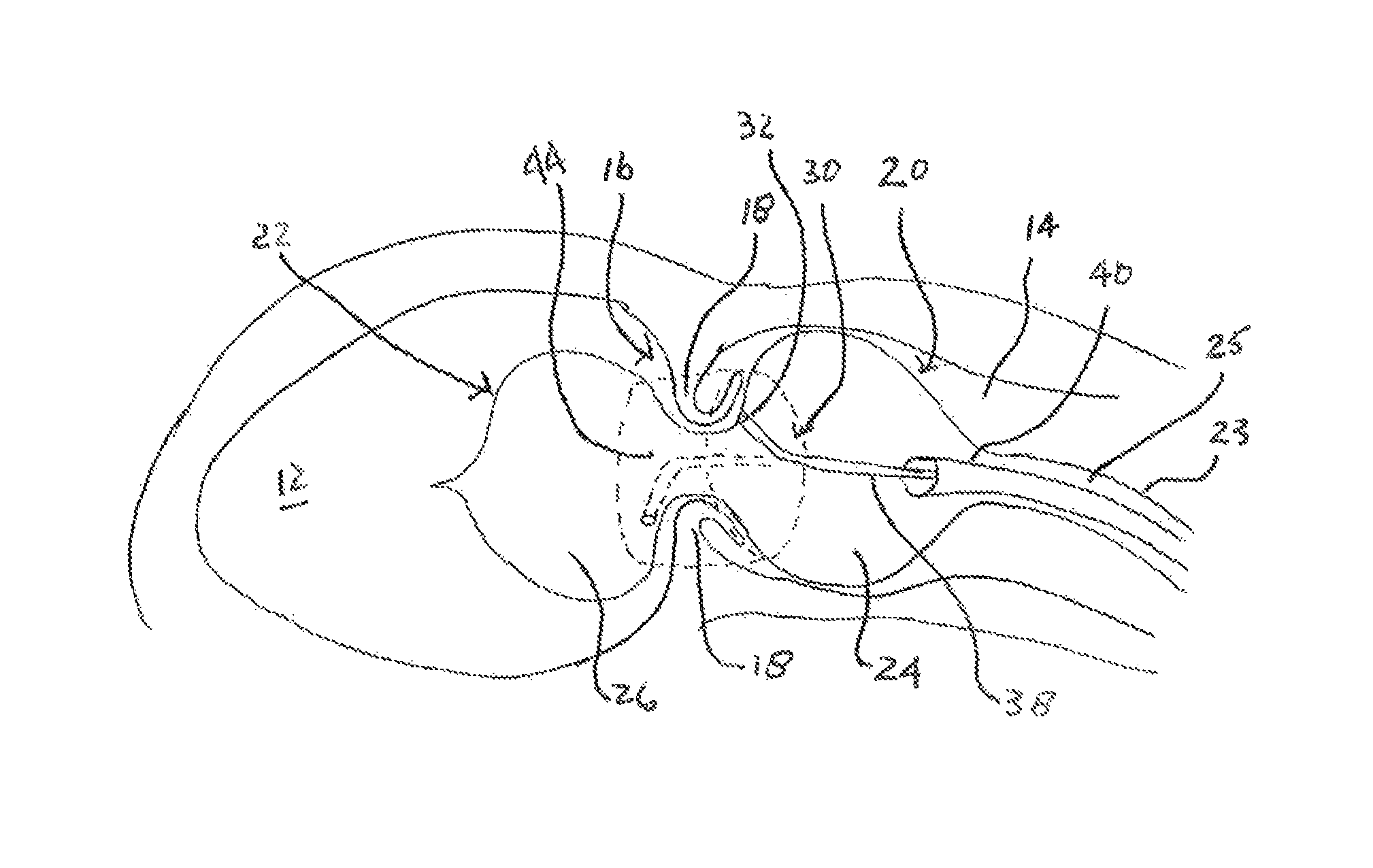
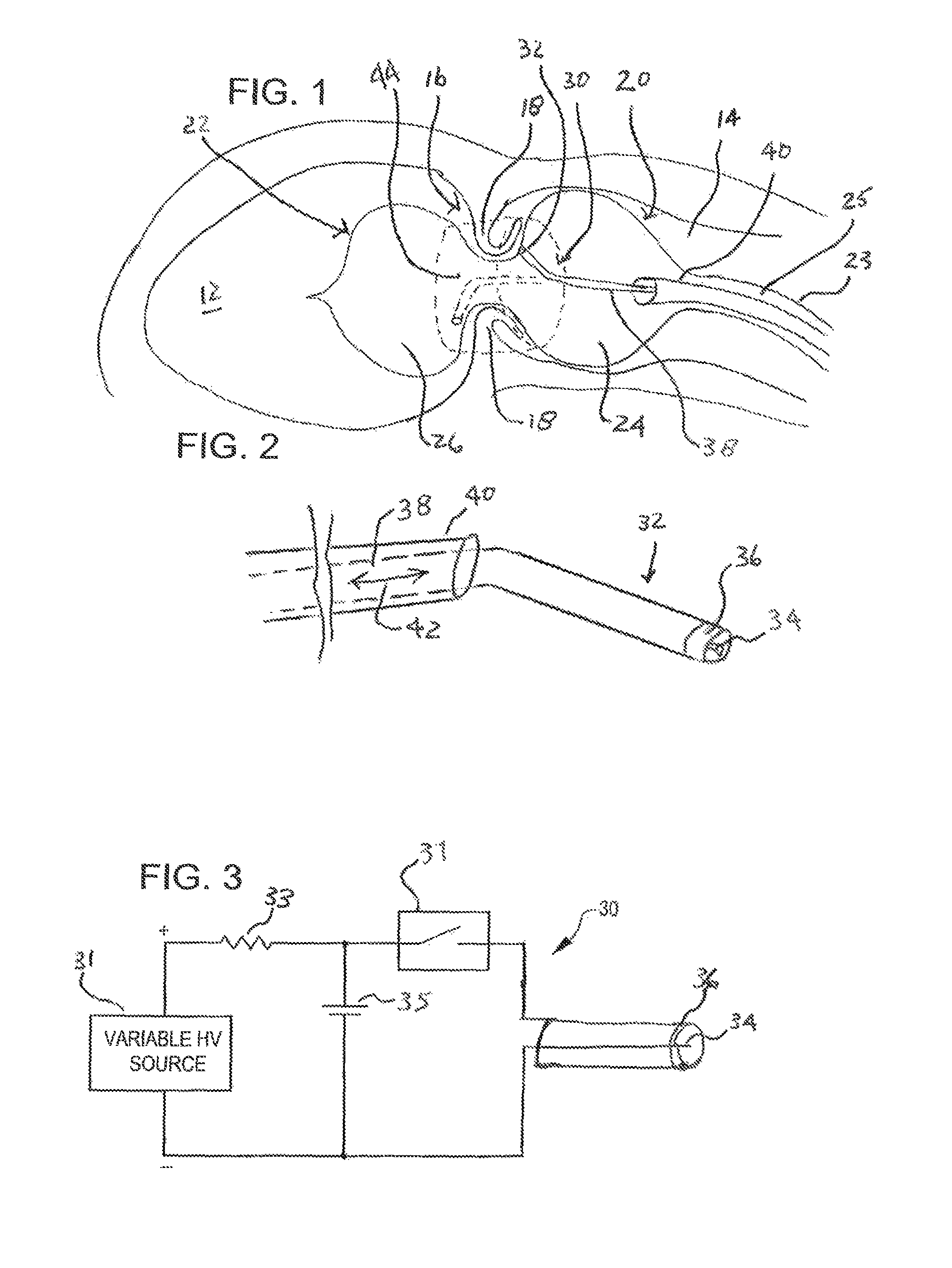
[0047]Referring now to FIG. 1, it is a cut away view of an aortic valve 16 of a heart with a treatment balloon 22 placed on both sides of the aortic valve leaflets 18. Also shown are the left ventricle 12 and the aorta 14 of the heart. Valves of the heart, such as the aortic valve 16 can become stenotic and calcified. More particularly, the opening of the valve defined by the leaflets can become stenotic and calcified. This can restrict the size of the opening as the valve leaflets 18 are thickened with calcium deposits and fibrotic tissue. The thickened leaflets 18 and smaller valve opening restrict blood flow from the heart creating excess work for the heart and poor cardiac output. As previously mentioned, current treatment includes replacement of the valve or attempts to stretch the valve annulus with a balloon.

[0048]FIG. 1 also shows a valvuloplasty system 20 embodying aspects of the present invention within the aortic valve 16 to treat the stenotic and calcified valve 16. The ...


PUM


Abstract

A valvuloplasty system includes a balloon adapted to be placed adjacent leaflets of a valve. The balloon is inflatable with a liquid. The system further includes a shock wave generator within the balloon that produces shock waves that propagate through the liquid for impinging upon the valve. The shock wave generator is moveable within the balloon to vary shock wave impingement on the valve.

Description

BACKGROUND OF THE INVENTION[0001]Aortic calcification, also called aortic sclerosis, is a buildup of calcium deposits on the aortic valve in the heart. This often results in a heart murmur, which can easily be heard with a stethoscope over the heart. However, aortic calcification usually doesn't significantly affect the function of the aortic valve.[0002]In some cases, though, the calcium deposits thicken and cause narrowing at the opening of the aortic valve. This impairs blood flow through the valve, causing chest pain or a heart attack. Doctors refer to such narrowing as aortic stenosis.[0003]Aortic calcification typically affects older adults. But when it occurs in younger adults, it's often associated with an aortic valve defect that is present at birth (congenital) or with other illnesses such as kidney failure. An ultrasound of the heart (echocardiogram) can determine the severity of aortic calcification and also check for other possible causes of a heart murmur.[0004]At pres...

Claims


Application Information

Patent Timeline
Patent Type & Authority Patents(United States)
IPC IPC(8): A61B17/22
CPCA61B17/22012A61B17/22022A61B2017/22024A61B2017/22025A61B2017/22062A61B2017/22098
Inventor ADAMS, JOHN M.GOFF, THOMAS G.
Owner SHOCKWAVE MEDICAL
Learn More