Rubber crawler
a crawler and rubber technology, applied in the field of rubber crawlers, can solve the problems of inability to drive the crawler, the service life of the rubber crawler is liable to be most affected, and the interference of the driving wheel in the crawler is liable to be undesirably caused
- Summary
- Abstract
- Description
- Claims
- Application Information
AI Technical Summary
Benefits of technology
Problems solved by technology
Method used
Image

Examples
first embodiment (
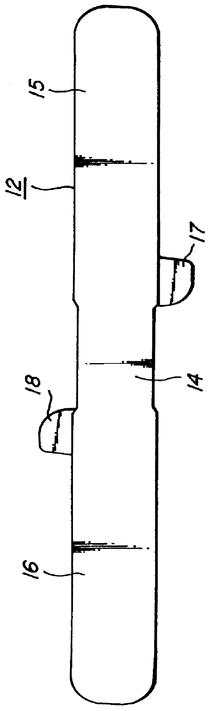
A first embodiment (24) of the rubber crawler according to the invention using the metal core 12 shown in FIGS. 3-6 is shown as a plan view in FIG. 7, as a bottom view in FIG. 8, as a right side view in FIG. 9 and as a section view in FIG. 10, respectively.
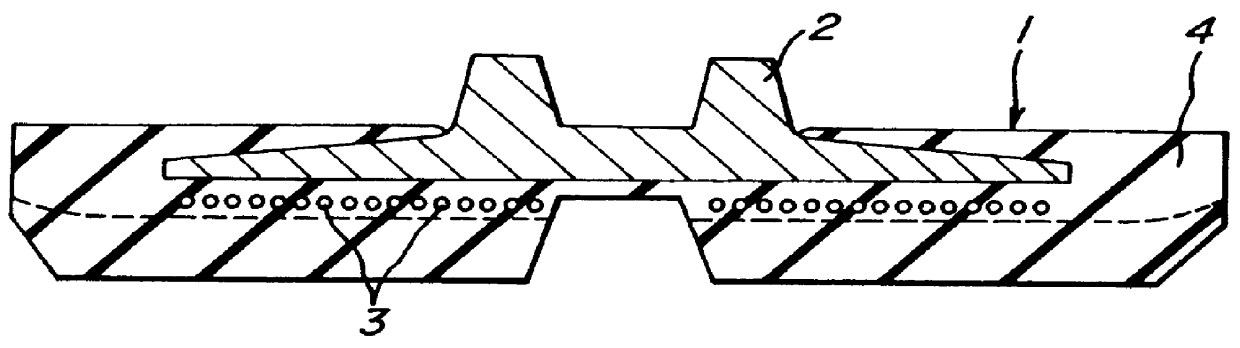
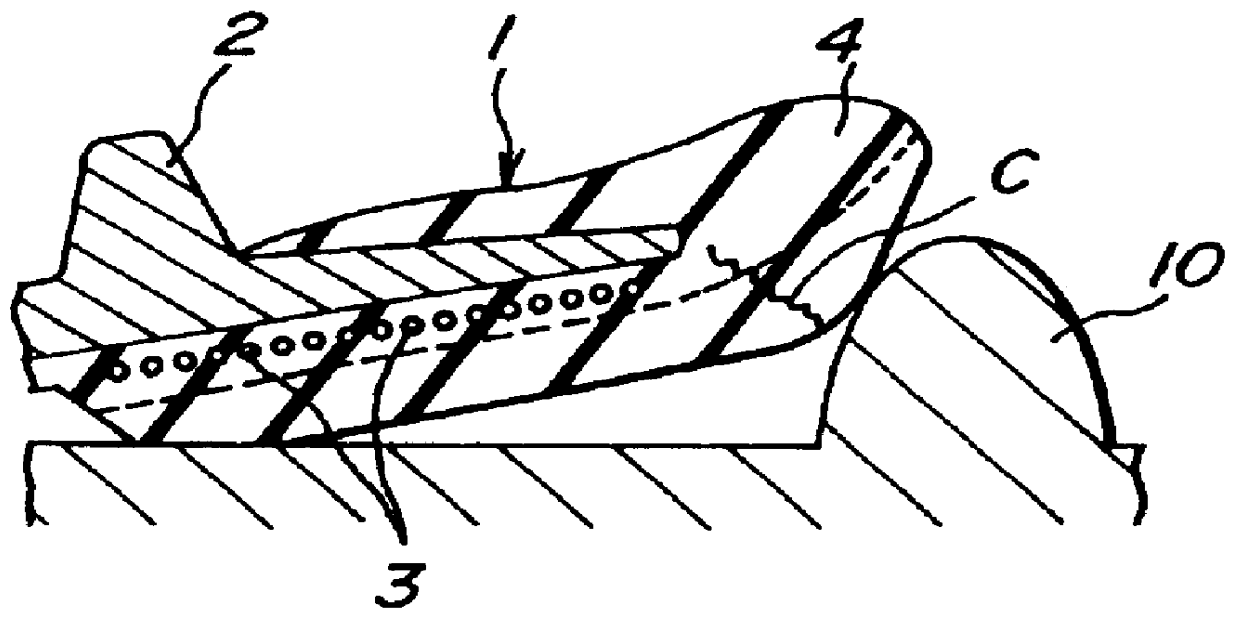
In the rubber crawler 24, numeral 26 is an endless rubber elastomer buried with a plurality of the metal cores 12 at a given pitch in the longitudinal direction thereof. A row of steel cords 27 arranged side by side are buried in the rubber elastomer 26 along a bottom surface of the wing portions 15, 16 of the metal core 12 in the longitudinal direction of the rubber elastomer 26. Therefore, widthwise end portions 28, 29 made of only rubber are formed outward from both ends of the metal core 12 in the rubber elastomer 26. Moreover, numeral 30 is a rubber lug formed on the outer peripheral surface of the rubber elastomer 26 at a side of contacting with ground and numeral 31 is a sprocket hole defined between the sprocket engaging p...
second embodiment (
A second embodiment (34) of the rubber crawler according to the invention is shown as a plan view in FIG. 11 and as a section view in FIG. 12. A second embodiment (40) of the metal core used in the rubber crawler 34 comprises a sprocket engaging portion 42, a pair of wing portions 43, 44 formed on both sides thereof, a pair of projections 45, 46 sandwiching the sprocket engaging portion 42, ribs 47, 48 formed on the wing portions 43, 44 toward the projections 45, 46 and bent portions 49, 50 formed by bending longitudinal ends of the wing portions 43, 44 to direct toward an inner peripheral side of the rubber crawler 34.
In the rubber crawler 34, numeral 35 is an endless rubber elastomer buried with a plurality of the metal cores 40 at a given pitch in the longitudinal direction thereof, numeral 36 is a rubber lug rubber lug formed on the outer peripheral surface of the rubber elastomer 35 at a side of contacting with ground, numeral 37 is steel cords arranged side by side in a row an...
third embodiment (
A third embodiment (84) of the rubber crawler according to the invention using the metal core 70 shown in FIGS. 13-16 is shown as a section view in FIG. 17.
In the rubber crawler 84, numeral 86 is an endless rubber elastomer buried with a plurality of the metal cores 70 at a given pitch in the longitudinal direction thereof. A row of steel cords 87 arranged side by side are buried in the rubber elastomer 86 along a bottom surface of the wing portions 73, 74 of the metal core 70 in the longitudinal direction of the rubber elastomer 86. Therefore, widthwise end portions 88, 89 made of only rubber are formed outward from both ends of the metal core 70 in the rubber elastomer 86. Moreover, numeral 90 is a rubber lug formed on the outer peripheral surface of the rubber elastomer 86 at a side of contacting with ground. A sprocket hole (not shown) is defined between the sprocket engaging portions 72 of the adjacent metal cores 70 in which sprocket teeth (not shown) of a driving wheel (not s...
PUM
 Abstract
Description
Claims
Application Information
 - Generate Ideas
- Intellectual Property
- Life Sciences
- Materials
- Tech Scout
- Unparalleled Data Quality
- Higher Quality Content
- 60% Fewer Hallucinations
Browse by: Latest US Patents, China's latest patents, Technical Efficacy Thesaurus, Application Domain, Technology Topic, Popular Technical Reports.
© 2025 PatSnap. All rights reserved.Legal|Privacy policy|Modern Slavery Act Transparency Statement|Sitemap|About US| Contact US: help@patsnap.com