Fuel injector for internal combustion engines and method for making same

a fuel injector and internal combustion engine technology, applied in the field of fuel injectors, can solve the problems of inconsistent atomization, insufficient atomization of internal combustion engines, and substantial influence of internal combustion engine performan

Inactive Publication Date: 2000-08-29
OUTBOARD MARINE +2
View PDF11 Cites 15 Cited by
  • Summary
  • Abstract
  • Description
  • Claims
  • Application Information

AI Technical Summary

Problems solved by technology

It has been found that the performance of internal combustion engines may be substantially affected by the quality and characteristics of the atomization or spray provided by such injectors.
However, heretofore known str...

Method used


Image

  • Fuel injector for internal combustion engines and method for making same
  • Fuel injector for internal combustion engines and method for making same
  • Fuel injector for internal combustion engines and method for making same

Examples


Embodiment Construction

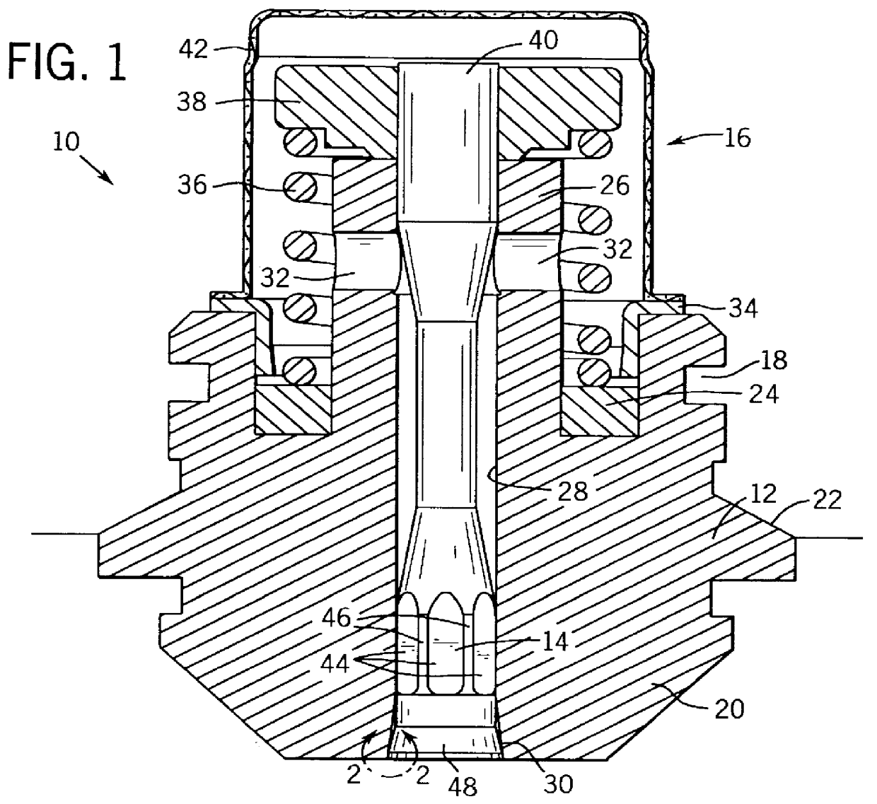
Turning now to the drawings and referring first to FIG. 1, an injector nozzle assembly 10 is illustrated in partial longitudinal section. Injector nozzle 10 is particularly adapted to receiving and delivering a flow of liquid fuel, such as gasoline, to a combustion chamber in which the injector nozzle is installed. The injector nozzle assembly includes a body 12 in which a poppet or pintel 14 is positioned for reciprocal movement. A return and securement assembly 16 is assembled between the poppet 14 and the body 12 to maintain the poppet in the body, to seal the poppet in the body as described below, and to force return of the poppet to a seated position during operation.

The body 12 of injector nozzle 10 is designed to be installed directly in an aperture in an injector structure (not shown), which is, in turn, secured in a combustion chamber, such as in the head of a cylinder of an internal combustion engine. Accordingly, the injector nozzle body 12 includes features for facilitat...


PUM

PropertyMeasurementUnit
Lengthaaaaaaaaaa
Angleaaaaaaaaaa
Angleaaaaaaaaaa

Abstract

A fuel injector nozzle includes a nozzle body and a poppet disposed in the body for reciprocating movement. The body has an internal bore surrounding the poppet. The internal bore tapers in a constant angle of taper from a front seating region to a fuel reservoir region. The poppet has a corresponding surface which diverges slightly from the bore. The surfaces of the bore and poppet form flow control surfaces which terminate in a sharp-edged orifice at the front face of the nozzle. When the poppet is displaced to an open or flow position, fuel is accelerated to the orifice and atomized into a combustion chamber.

Description

1. Field of the InventionThe present invention relates generally to the field of injectors for internal combustion engines. More particularly, the invention relates to a novel geometry for a nozzle and poppet arrangement in an injector, particularly well suited for single fluid, pressure surge, direct in-cylinder fuel injection.2. Description of the Related ArtIn the field of internal combustion engines, various structures have been proposed over the years and are presently in use for providing the desired mix of fuel and gas, typically air, in combustion cylinders. In a particularly useful family of structures, an injector is fed with fuel and expresses fuel directly into a combustion cylinder in a measured and properly timed sequence. The fuel is atomized upon injection into the cylinder and is rapidly ignited by a spark plug to provide the rapid expansion needed to drive the engine.It has been found that the performance of internal combustion engines may be substantially affected...

Claims


Application Information

Patent Timeline
IPC IPC(8): B24B15/00B24B15/02F02M61/00F02M61/16F02M61/08F02M61/18
CPCB24B15/02F02M61/08F02M61/168Y10T29/49433Y10T29/49432
Inventor RADUE, MARTIN L.PARRISH, SCOTT E.PELTIER, DANIEL E.HELLMICH, WOLFRAM
Owner OUTBOARD MARINE
Why Eureka
Try Eureka