Plumbing coupling and method of use

a technology of coupling and ply, which is applied in the direction of service pipe systems, container discharge methods, drawing-off water installations, etc., can solve the problems of laborious process, high cost of test valves, and high cost of wear and tear, and achieve the effect of quick and inexpensive installation of couplings

Inactive Publication Date: 2000-09-12
CORRALEJO GREGORY J
View PDF5 Cites 7 Cited by
  • Summary
  • Abstract
  • Description
  • Claims
  • Application Information

AI Technical Summary

Benefits of technology

The present invention is directed to a plumbing coupling which can be used to pressure test conventional plumbing drainage lines, and which can remain in the line after testing. The invention permits a plumber to quickly and inexpensively install the coupling and test the system, and then return the system to its normal configuration. The coupling uses a resilient cylindrical body to connect two pipes. The body has a through-slit which extends part way around its perimeter. A flat closure plate is inserted into the through-slit to block the flow of water through the body. A metal sleeve connects around the body and installed closure plate to both strengthen the joint and tighten the watertight seal. At the completion of testing, the sleeve is removed, the closure plate is withdrawn, and the sleeve is reattached around the body, the sleeve and body permanently remaining as a part of the drainage system.

Problems solved by technology

This procedure is troublesome in that the test valves are expensive and tend to wear out frequently, and the process is labor intensive by virtue of the necessary cut, insertion, removal, and permanent coupling installation steps.

Method used


Image

  • Plumbing coupling and method of use
  • Plumbing coupling and method of use
  • Plumbing coupling and method of use

Examples


Embodiment Construction

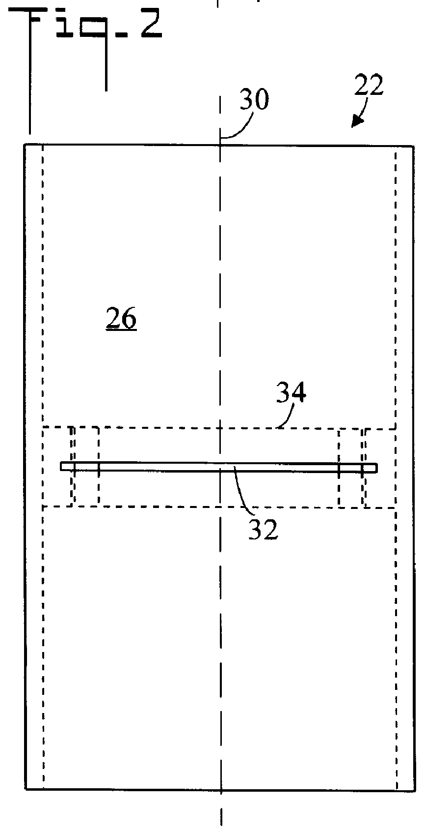
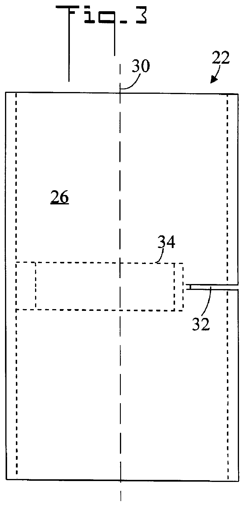
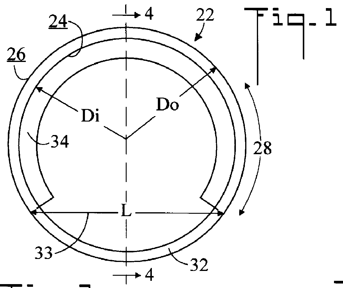
Referring initially to FIGS. 14, 15, and 16 there are illustrated reduced perspective and two top plan views respectively of a plumbing coupling in accordance with the present invention, generally designated as 20. Now referring to FIGS. 1 through 4, there are illustrated top plan, front elevation, side elevation, and cross sectional view respectively of a substantially cylindrical body 22 of plumbing coupling 20. Body 22 has an inner surface 24, an outer surface 26, an outer perimeter 28, a longitudinal axis 30, an inner diameter Di, and an outer diameter Do. Body 22 is fabricated from a resilient material, neoprene rubber being preferred. Body 22 further includes a through-slit 32 which is oriented substantially perpendicular to longitudinal axis 30. Through-slit 32 penetrates the wall of body 22, and partially extends around outer perimeter 28, and defines a chord 33 having a length L. In a preferred embodiment, through-slit 32 extends between one-half and one-fourth of the way a...


PUM


Abstract

A plumbing coupling (20) for connecting two lengths of pipe (500) includes a cylindrical body (22) having a circumferential through-slit (32) extending part of the way around its perimeter (28). A closure plate (36) is selectively insertable into the through-slit (32) so as to abut the inner surface (24) of body (22) and block the flow of water through the plumbing coupling (20). A sleeve (42) is selectively wrapable around body (22) to tightly seal the closure plate (36). To conduct a pressure test, closure plate (36) is inserted and sleeve (42) attached. To return the plumbing line to normal use, middle portion (43) of sleeve (42) is peeled back, closure plate (36) is removed, and middle portion (43) of sleeve (42) is reattached. Body (22) is fabricated from a resilient material which conforms to edge (38) of closure plate (36).

Description

The present invention pertains generally to plumbing, and in particular to devices which are utilized to test plumbing drainage systems.Test fixtures for the pressure testing of plumbing drainage or vent pipes and stacks are well known in the art. As required by building codes in the installation of plumbing systems, particularly waste or vent pipes in buildings, it is necessary to pressure test the pipes for leaks. The present method is to cut the pipe an temporarily insert a complicated test valve arrangement (called a "wye" having a "double test plug") which blocks the pipe. A head of water is then applied upstream of the valve, and the drainage line is checked for leaks. After the test, the test valve must be removed and replaced with a permanent coupling. This procedure is troublesome in that the test valves are expensive and tend to wear out frequently, and the process is labor intensive by virtue of the necessary cut, insertion, removal, and permanent coupling installation st...

Claims


Application Information

Patent Timeline
Patent Type & Authority Patents(United States)
IPC IPC(8): F16L55/10
CPCF16L55/10Y10T137/0441
Inventor CORRALEJO, GREGORY J.
Owner CORRALEJO GREGORY J
Why Eureka
Try Eureka