Apparatus and method for precisely aligning and welding two pieces of weldable material

a technology of weldable materials and apparatuses, applied in the direction of soldering apparatus, manufacturing tools,auxillary welding devices, etc., can solve the problems of time-consuming and difficult tasks, and affecting the welding process

Inactive Publication Date: 2000-09-19
ARC MACHINES
View PDF6 Cites 9 Cited by
  • Summary
  • Abstract
  • Description
  • Claims
  • Application Information

AI Technical Summary

Problems solved by technology

Moreover, misalignment can result in a leaky junction that destroys the purity of the substance flowing through the tubing and creates a potentially dangerous external environment if the substance flowing through the tubing is toxic.
Maintaining proper alignment during the conventional welding process, however, is a time-consuming and difficult task.
The pieces of weldable material to be aligned and welded must be clamped tightly in alignment before and during the welding process, or the pieces will tend to slip out of alignment before the weld is completed.
Conventional orbital weld heads do not solve this slippage problem.
Orbital welding however, does not solve the problem of misalignment.
To the contrary, the conventional weld head on a standard orbital welder has such little clamping surface area that proper alignment of the pieces of weldable material is often the most significant and time-consuming challenge facing the technician operating the welder.
In addition, because of the construction of the conventional orbital weld head, the technician has an extremely limited view of the junction to be welded as he attempts to align the two pieces of weldable material to each other and position the junction of the two pieces in line with the electrode.
The manual performance of these tasks is far from ideal for applications requiring strict alignment and is very time-consuming.
An attempt to excessively tighten the clamps on the weld head to overcome this problem usually results in the formation of clamping marks in the weldable material and may result in actual tube deformation.
Even when using tack welding, proper alignment is critical, and therefore, tack welding, by itself, does not address the problem of creating acceptable alignment in a time efficient manner.
Although tack welding effectively joins two pieces together prior to performing an orbital weld and makes the orbital welding process much simpler, throughput or productivity, measured in welds per hour, is still limited by the amount of time it takes to align the pieces in preparation for the tack weld.
Although Applicant's prior invention is a definite improvement over the prior art, it still is not an ideal solution, because once the tack weld is completed, the technician must then spend time switching instruments to perform a full weld with a conventional orbital weld head.

Method used


Image

  • Apparatus and method for precisely aligning and welding two pieces of weldable material
  • Apparatus and method for precisely aligning and welding two pieces of weldable material
  • Apparatus and method for precisely aligning and welding two pieces of weldable material

Examples


Embodiment Construction

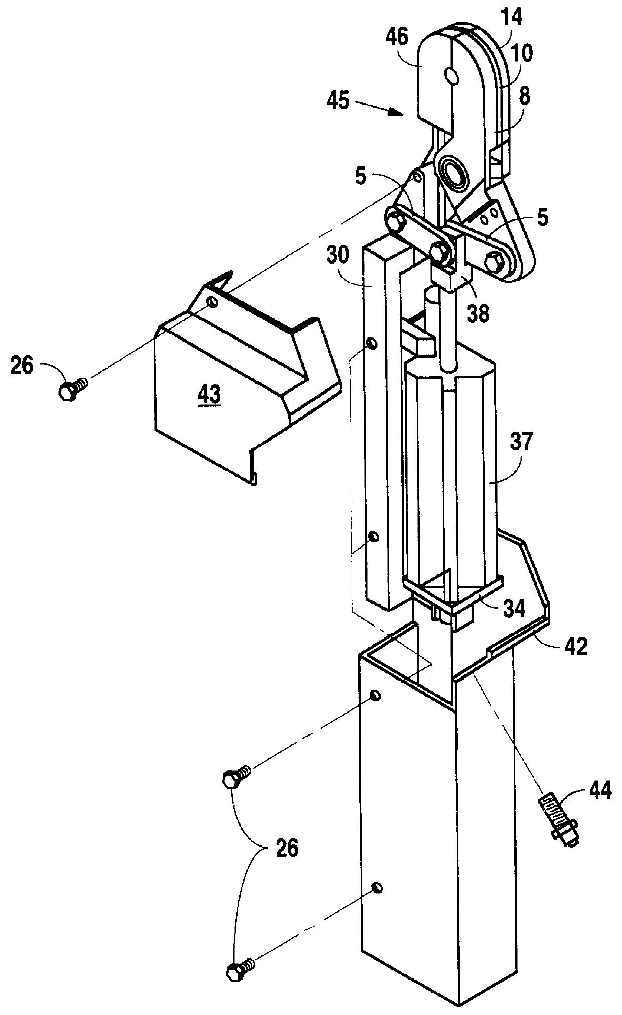
FIG. 1 is a perspective view of the alignment / welding device in the closed position;

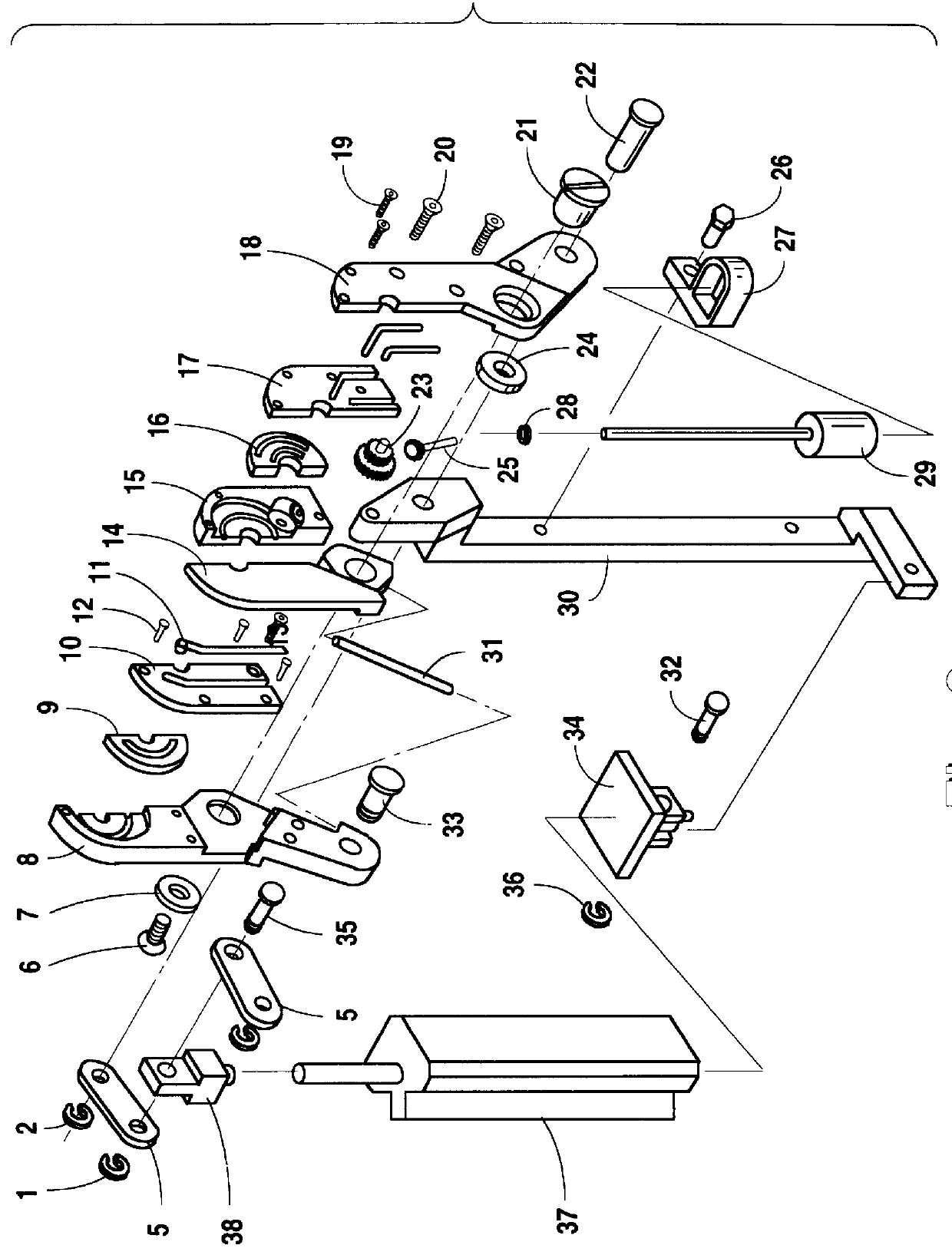
FIG. 2 is an exploded view showing the arrangement of the various components that comprise the preferred embodiment of the alignment / welding device;

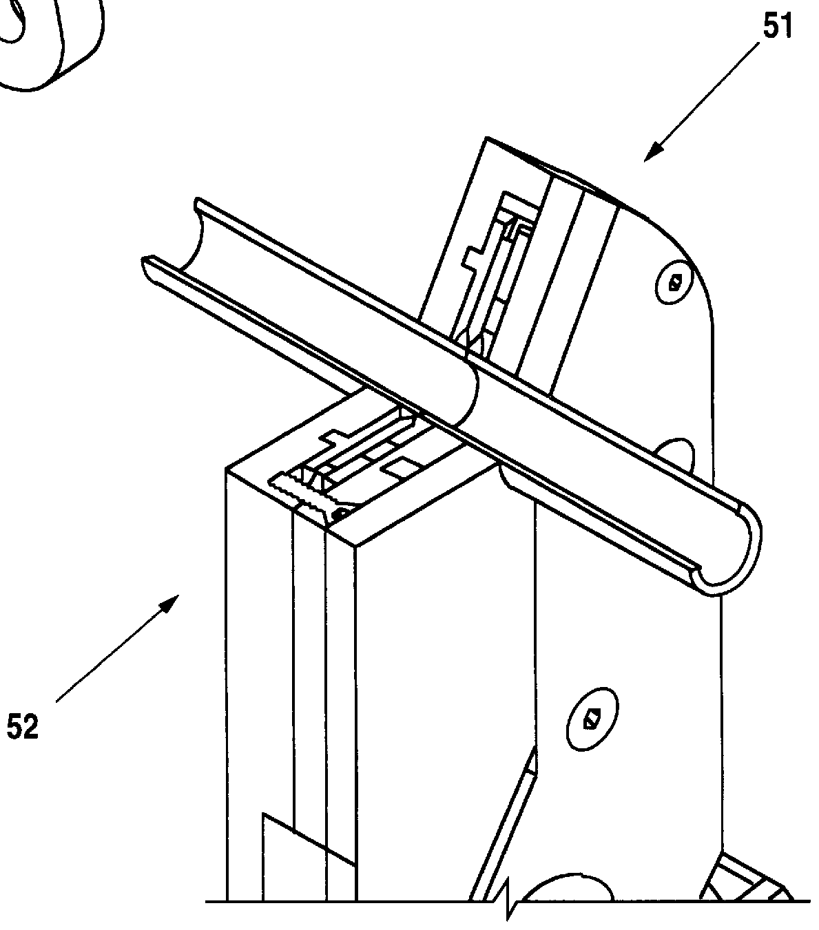
FIG. 3 is a perspective view of the alignment / welding device showing the device being closed from a fully open position to a partially closed first position, wherein the pre-lock clamping jaw rests against the first jaw;

FIG. 4 is a partial cut-away view of a portion of the alignment / welding device in the closed position with welding material present;

FIG. 5 is a depiction of the distance "d1" which is used to measure alignment tolerances.

FIG. 6 is an exploded view of the electrode / rotating gear assembly of the alignment / welding service.

FIG. 7 is a perspective view of a portion of the alignment / welding device, illustrating the manner in which the electrodes are wired.

FIG. 8 is a cut-away view of a portion of the alignment / welding device with a piece of weld...


PUM

PropertyMeasurementUnit
weldableaaaaaaaaaa
separation distanceaaaaaaaaaa
diameteraaaaaaaaaa

Abstract

Applicant's invention includes an apparatus and associated method for precisely aligning two pieces of weldable material and welding the two pieces, the apparatus contains means for independently securing the two pieces of weldable material and for centering the junction of the two pieces in line with the welding electrodes.

Description

1. Field of the InventionApplicant's invention relates to the joining together of two pieces of material by welding.2. Background InformationWelding is a well-known and widely-used method used to permanently join together two pieces of metal tubing or other weldable material. To accomplish a weld of high integrity, the two pieces to be joined together must be properly aligned.Misalignment during welding creates discontinuities at the abutment junction of the two pieces of weldable material that can serve as havens for particle impurities. The existence of these particle "sites" is intolerable when the welding is being performed in connection with ultra-pure applications such as are common in the semiconductor industry.Moreover, misalignment can result in a leaky junction that destroys the purity of the substance flowing through the tubing and creates a potentially dangerous external environment if the substance flowing through the tubing is toxic. Thus, it is highly desirable to min...

Claims


Application Information

Patent Timeline
Patent Type & Authority Patents(United States)
IPC IPC(8): B23K11/06B23K37/053
CPCB23K11/066B23K37/0533B23K2201/06B23K2101/06
Inventor GUERRINA, MICHAEL
Owner ARC MACHINES
Why Eureka
Try Eureka