Arrangement in vehicle

Inactive Publication Date: 2000-10-03
KARHUMAKI JORMA
View PDF15 Cites 22 Cited by
  • Summary
  • Abstract
  • Description
  • Claims
  • Application Information

AI Technical Summary

Problems solved by technology

The problem in current vehicles intended for display purposes is that it is difficult to arrange reasonable visibility and audibility for all participants in small premises.
A presentation taking place at the front of the showroom is difficult to follow from the rear parts of the vehicle.
The problem with this solution is, however, that the vehicle is restricted to be used solely as a mobile auditorium.
It is not suitable, e.g., for conferences, buff

Method used


Image

  • Arrangement in vehicle
  • Arrangement in vehicle
  • Arrangement in vehicle

Examples


Embodiment Construction

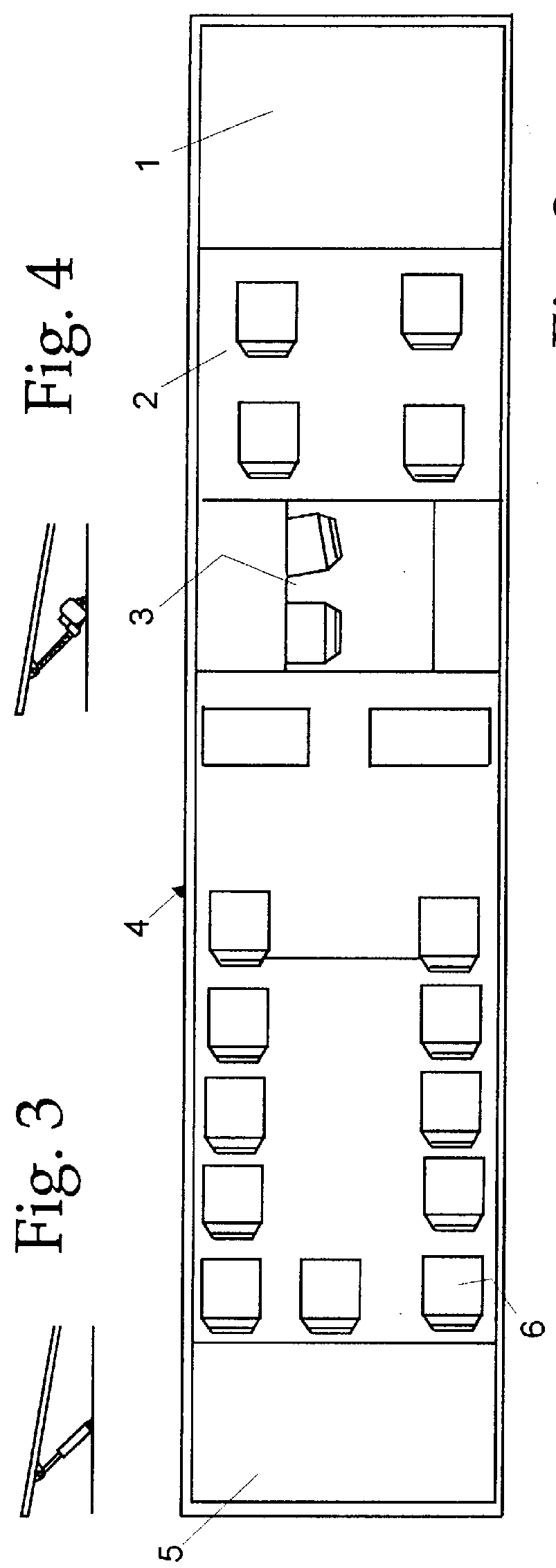
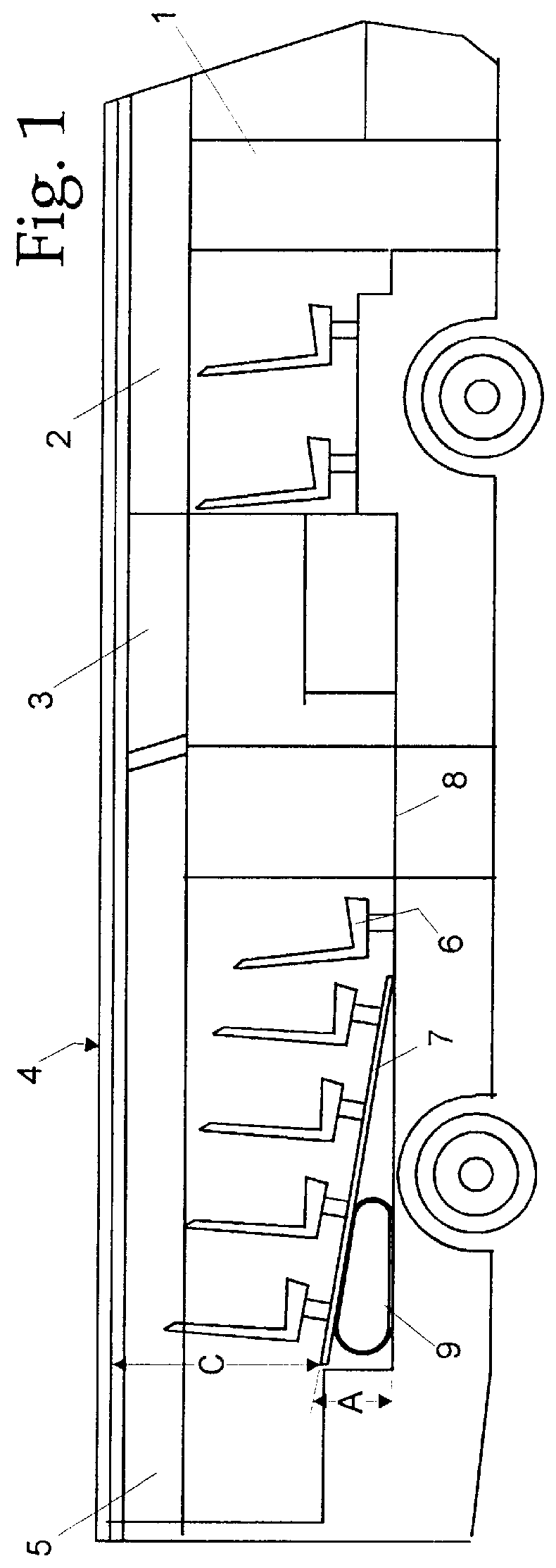
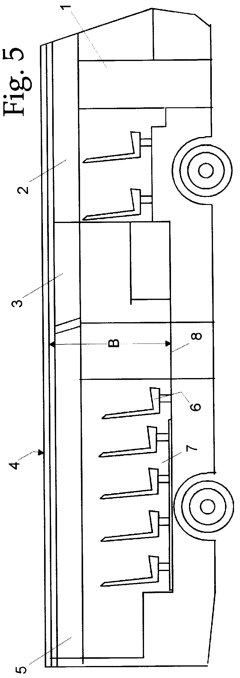
FIG. 1 schematically shows a multi-use vehicle constructed in the frame of a bus. A bus is a natural chassis to be used in the arrangement of the invention, but the invention can be applied to other ground equipment, such a trailers, trucks and vans. The vehicle shown in the figure comprises, starting from its front end, a cab 1, a cabinet 2, a kitchen 3, an actual showroom 4, and service spaces 5 at the rear of the vehicle, including e.g. a toilet and a trunk. The cab 1 is preferably isolated from the rest of the space, allowing the driver to concentrate on his tasks. The cabinet 2 is similarly separable by curtains, movable partitions or the like from the rest of the space, allowing it to be used as a separate private passenger cabin or, e.g. the conference room of a small group. The vehicle of FIG. 1 further comprises a kitchen, enabling catering during exhibition. If required the kitchen 3 can also be used as a product display and showroom. As is evident, the showroom 4 operates...


PUM


Abstract

The invention relates to an arrangement in a vehicle intended and equipped for various display purposes. The arrangement comprises means for tilting the vehicle floor in at least part of the vehicle. This way the vehicle can be rapidly and flexibly formed into an auditorium with a tilted floor, and a conference or showroom with a level floor.

Description

1. Field of the InventionThis invention relates generally to show rooms and the like, and is more particularly concerned with a vehicle adapted and equipped for various displays and entertainment purposes, the vehicle comprising a showroom provided with seats in at least two successive rows.2. Discussion of the Prior ArtThe prior art includes various wheeled exhibition equipment, vehicle mounted showrooms, entertainment and conference rooms and other "road show equipment", which can be conveyed or transported on their own platform to the customer. Such showrooms are usually built on a bus chassis, but constructions built on trailers are also in use. The purpose of such equipped showrooms is to transport a company or a piece of equipment to be displayed to a customer, providing better service to the customers. When the premises are transported to the customer's yard, the customer does not have to spend time and money traveling. The solution is also advantageous from the point of view...

Claims


Application Information

Patent Timeline
IPC IPC(8): B60P3/025
CPCB60P3/0252
Inventor KARHUMAKI, JORMA
Owner KARHUMAKI JORMA
Why Eureka
Try Eureka