Flow directed catheter having radiopaque strain relief segment

a flow-directed catheter and strain relief technology, which is applied in the direction of catheters, intravenous devices, needles, etc., can solve the problems of difficult the inability to provide sufficient flexibility of the catheter, and the inability of the physician to determine the exact position of the transition area

Inactive Publication Date: 2000-10-03
CODMAN & SHURTLEFF INC
View PDF42 Cites 26 Cited by
  • Summary
  • Abstract
  • Description
  • Claims
  • Application Information

AI Technical Summary

Problems solved by technology

With extremely small vessels it is often not possible to provide a catheter with sufficient flexibility for passage through the tortuous vasculature while still providing sufficient rigidity to steer, or torque, the distal end of the catheter to a desired site.
One problem with currently available flow directed catheters is that with these devices the physician is unable to determine the exact position of the transition area between the relatively stiff proximal portion of the catheter and the floppy distal portion of the catheter.
With the inability to determine the location of this transition area it is very difficult to determine which portion of the catheter may be steered by torquing on the hub of the catheter and which portion of the catheter may not be so steered but may simply be permitted to be directed by the flow of blood through the blood vessel.
In addition, it is difficult for the doctor to prevent kinking of the relatively soft floppy portion of the catheter as this portion of the catheter passes through the blood vessel if the doctor is unable to discern whether a particular portion of the catheter is formed of a relatively stiff material or a very floppy material.

Method used


Image

  • Flow directed catheter having radiopaque strain relief segment
  • Flow directed catheter having radiopaque strain relief segment
  • Flow directed catheter having radiopaque strain relief segment

Examples


Embodiment Construction

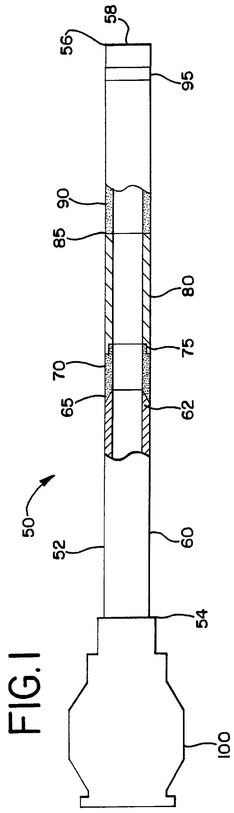
FIG. 1 illustrates the assembled flow directed catheter 50 having a main tubular body 52 with a proximal end 54 and a distal end 56 and an inner lumen 58 extending there through. The main tubular body 52 is constructed from four segments; a relatively stiff proximal shaft segment 60, a radiopaque strain relief segment 70, a proximal floppy segment 80 and a soft distal floppy segment 90.

The relatively stiff proximal shaft segment 60 of main tubular body 52 is preferably made from a high durometer polymeric material or a polymer coated metallic hypotube. Suitable polymers for the proximal shaft segment 60 include biologically compatible polymers such as nylon, polyethylene, polyester, polyurethane, silicone and the like. The durometer of the proximal shaft segment 60 is between 60 D and 90 D and is preferably 75 D. The proximal shaft segment 60 provides proximal support for flow directed catheter 50, enabling pushability without the need of a guidewire. The proximal shaft segment 60 c...


PUM


Abstract

A flow directed catheter for use in medical diagnostic or therapeutic procedures having a strain relief segment between the relatively stiff proximal section of the catheter and the floppy distal tip portion in which the strain relief segment is formed of a polymeric material containing a radiopaque agent.

Description

1. Field of the InventionA flow directed catheter for use in medical diagnostic or therapeutic procedures having a strain relief segment between the relatively stiff proximal section of the catheter and the floppy distal tip portion in which the strain relief segment is formed of a polymeric material containing a radiopaque agent.2. Background ArtIn order to diagnose the extent of coronary artery disease angiography procedures are used to view the blood flow through selected blood vessels. In carrying out this procedure diagnostic catheters are introduced into the blood vessels of a patient and are advanced over a guidewire through the vascular system of the patient until the distal end of the catheter is steered into the particular blood vessel to be examined.In view of the fact that the human vasculature is quite tortuous it is essential that a diagnostic catheter be capable of being steered by torquing the proximal hub of the catheter in order to direct the catheter through the v...

Claims


Application Information

Patent Timeline
Patent Type & Authority Patents(United States)
IPC IPC(8): A61M25/06A61M25/00A61M25/01A61M25/098
CPCA61M25/0054A61M25/0662A61M25/0125A61M25/0108A61M2025/0098
Inventor MARTINEZ, SUSANA M.SHKOLNIK, BORIS
Owner CODMAN & SHURTLEFF INC
Why Eureka
Try Eureka